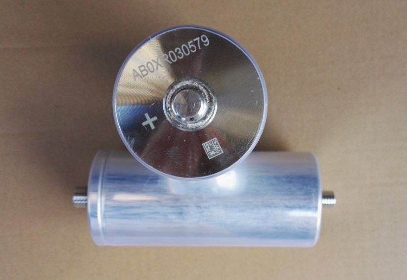
Application conductive polymer capacitor
Technical note
As aluminum solid capacitor with conductive polymer is different as the common capacitors which use electrolyte as cathode. Please note the following points in order to take full advantages of the aluminum solid capacitor with conductive polymer and ensure the most stable quality possible.
Crucial precautions
1. Polarity
The solid aluminum electrolytic capacitor with positive and negative electrodes.
Do not reverse the polarity when using. If happened, increased leakage current or a decreased life span may result.
2. Prohibited circuits
The leakage current may become greater even if the soldering conditions adhere to the specification requirements. Therefore, do not use the capacitors in the following circuits because trouble or failure may occur.
a) High impedance circuits
b) Coupling circuits
c) Time constant circuits
d) Do not use the capacitors in circuits except those above if changes in the leakage current affect circuit operations.
3. Compliance with rated performance
The aluminum solid capacitor with conductive polymer must be used under the rated voltage.
Over-voltage exceeding the rated voltage should not be applied since it may cause a short circuit.
4. Considerations when soldering
The soldering conditions are to be within the range prescribed in specifications.
If the specifications are not followed, there is a possibility of the cosmetic defection, the intensive increase of leakage current, and the capacitance reduction.
Applied voltage when circuit design
It can be applied with the rated voltage.
Sum of the DC voltage value and the ripple voltage peak value must not exceed the rated voltage.
When DC voltage is low, negative ripple voltage peak value must not become a reverse voltage
that exceeds 10% of the rated voltage.
Using the capacitors within 20% of the rated for applications which may cause the reserve voltage during the transient when the power is turned off or the source is switched.
Capacitor insulation
Insulation in the laminate resin is not guaranteed. Be sure to completely separate the case, negative lead terminal, positive lead terminal and PC patterns will each other.
Prohibited circuits
The leakage current may become greater even if the soldering conditions adhere to the specification requirements. Therefore, do not use the capacitors in the following circuits because trouble or failure may occur.
a) High impedance circuits
b) Coupling circuits
c) Time constant circuits
d) Do not use the capacitors in circuits except those above if changes in the leakage current affects circuit operations.
Things to be noted before mounting
The leakage current value after soldering may increase a little, from a few μA to several hundred μA, depending on the soldering conditions (preheating and solder temperature and time, PCB material and thickness, ect.). The leakage current can be reduced through self-repair by applying voltage.
Handing after soldering
Do not subject the capacitors itself to excessive stress after soldering.
Do not tilt, bend or twist the capacitors after it has been soldered on the PCB.
Precautions with completed board
(1) Do not touch the lead terminals of the capacitors directly.
(2) Do not use electric conductive to cause short circuit between the capacitors lead terminal. Do not subject the capacitors to conductive solutions such as acid and alkaline water solutions.
(3) Check the installation environment of the board the capacitor is installed in.
(4) Age the board at conditions that fall bellow the capacitors ratings.
Contingency failure
The electrolyte, electrolytic paper, sealing rubber, and sleeve used in the capacitors are all combustible. When the current is extraordinarily large after a short circuit, in the worst case, the shorted-out section in the lead terminal or inside the capacitor may ignite the rubber. Pay attention to the capacitor mounting method, mounting position, pattern design, ect.
General introduction of polymer capacitors
Features
●Long life
20000h life at 85°C can be expected, suitable for long-operating industrial equipments.
●Stable temperature characteristics
Its ESR has stable characteristics from -55°C to 105°C (partly 125°C), suitable for applications used at low temperature (under 0°C)
●Low ESR obtained by using conductive polymer electrolyte
Suitable as a smoothing capacitor, enabling miniaturizing switching power supplies, because it allows large ripple current.
Suitable as a backup capacitor for the circuits that consume large current at a high speed.
Suitable as a decoupling capacitor, because its impedance has ideal frequency characteristics.
●RoHS Compliant
All the models are RoHS compliant products.
●High safety
More difficult to ignite and "smoke" than a tantalum electrolytic capacitor.
Estimation of life time
Liquid electrolytic capacitor: Life will finish when electrolyte is drying out, L=L0x2 10 (LO: Life at 105°C)
|
Solid electrolytic capacitor: Long life, solid electrolyte, no drying concern.L=L0x 10 20 (LO: Life at 105°C) Liquid electrolytic capacitor |
Solid electrolytic capacitor |
|||||
|
|
105°C |
2000h |
105°C |
2000h |
|
|
|
|
95°C |
4000h |
95°C |
6324h |
|
|
|
|
85°C |
8000h |
85°C |
20000h |
|
|
|
|
75°C |
16000h |
75°C |
63245h |
|
|
|
|
65°C |
32000h |
65°C |
200000h |
|
|

 Tel:86 0513 65085106 Fax:86 0513 81164838