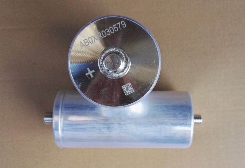
Electrolytic capacitors
Aluminium electrolytic capacitors
Basic construction
The aluminium electrolytic capacitor consists of two foils interleaved with an absorbent paper, and wound tightly into a cylinder. The positive foil, or anode, is made from pure aluminium foil on the surface of which aluminium oxide dielectric has been formed electrolytically. The foil has been etched to increase the effective surface area, and the area of the anode is typically 30–100 times larger than the plan area of the foil.
Figure 1: Schematic of dielectric structure in an aluminium electrolytic capacitor

The other plate is a combination of high-absorption paper impregnated with an electrolyte, in contact with a cathode foil. The electrolyte is there to make good contact with the anode, by permeating its etched structure, and also to repair any flaws in the oxide layer when the capacitor is polarised. The function of the aluminium cathode foil is to reduce the series resistance of the capacitor by making contact with the paper over a wide area.
The cathode foil itself has a thin oxide film, and is typically etched to increase the surface area slightly. You may have worked out this gives some capacitance between foil and electrolyte, so that the overall capacitance is that of the anode plus that of the cathode in series. You will be right to think that, but in practice the cathode film is very thin and its capacitance consequently very high.
The anode and cathode foils are interleaved with paper and wound into a cylinder as shown in Figure 2. During the winding process, aluminium tabs are attached to each foil to provide electrical contact. In large capacitors, the next process would be to add the terminal deck, complete with terminals, which are attached to the tabs before the deck is folded down to rest on top of the winding.
Large aluminium electrolytic capacitors with tag terminations

The complete winding is then impregnated with an electrolyte, before being housed in a suitable container, usually an aluminium can, and sealed. Before being sleeved and packed, capacitors are first aged. The purpose of this stage is to repair any damage in the oxide layer, and thus reduce the leakage current to very low levels. Damage to the oxide layer can occur due to slitting of the anode foil after forming, attaching the tabs to the anode foil, or minor mechanical damage caused during winding. Normally carried out at the rated top temperature to the capacitor, ageing applies voltage to the device through a current-limited supply, a process that may take several hours to complete.
We have mentioned the ‘electrolyte’, and this is important, because the choice of electrolyte determines some of the capacitor characteristics. For example, a mixture based on ethylene glycol and water will freeze at very low temperatures. Such ‘wet’ capacitors must be operated upright and tend to have lower operating voltages. A number of similar electrolytes are to be found, many of which have a ‘gel’ consistency. So-called ‘dry’ electrolytic capacitors use electrolytes such as manganese oxide, but tend to have lower volumetric efficiency.
Figure 2: Construction of a wound aluminium electrolytic capacitor

The original aluminium electrolytic construction produces a capacitor with radial leads for through-hole insertion. This style is made in volume and very cost-effective: you will find many circuits that use small radial electrolytic capacitors, either self-supported or with additional mechanical strengthening provided by a dispensed silicone rubber surround/underfill. For power supplies and similar applications demanding high values of capacitance, the components are large and heavy, and will be fixed by a clamp or tie wrap around the body.
Small radial format aluminium electrolytic capacitor

Aluminium electrolytic capacitors in a surface mount package

Increasingly, parts are modified with tabs underneath for surface mounting, although large value parts still have the disadvantage of a relatively high ‘profile’ above the board. This is significant not only because of the space taken up, but also because lateral forces on the body (due for example to vibration) result in high stress on the solder joints. Components have thus been developed with four tabs (instead of two).
Other types have the chip-type format shown in Figure 3, where the body is encapsulated in plastic, but these are generally more expensive. Attempts have also been made to produce a ‘solid aluminium’ electrolytic capacitor similar to the tantalum part, but these have not been successfully implemented.
Figure 3: Construction of an SM aluminium electrolytic capacitor

Tantalum electrolytic capacitors
The very first tantalum capacitors used the same etched foil principle as the aluminium electrolytic. However, they differed in their choice of electrolyte. Believe it or not, wet tantalum capacitors contain sulphuric acid! In order to contain this corrosive material, wet tantalum capacitors use a solid silver case to contain the wound foil, and the connections are made through glass-to-metal seals. The resulting capacitor is extremely effective, with low ESR, and has a reputation for reliability. It is not cheap!
The solid tantalum capacitor takes a totally different approach, creating a sponge of high purity tantalum powder around a tantalum wire by pressing tantalum powder into a small slug around the lead and then sintering it at high temperature (around 1800°C).
The powder from which tantalum capacitors are made is of pure tantalum metal, with a typical particle size of 10µm. Differently shaped particles are available for different applications, depending on the voltage and capacitance required – if you want to know the detail of the process, read John Gill’s paper Basic Tantalum Capacitor Technology on the AVX website.
At this stage, we have a tantalum wire attached to a slug of tantalum sponge and the next stage is producing the dielectric layer of tantalum and oxide. The slugs are dipped into a weak acid, such as phosphoric acid, at elevated temperature, and the voltage gradually increased (whilst controlling the current) in order to create an oxide layer of the correct thickness.
The next stage is to produce the cathode plate, making contact to every part of the top surface of the oxide. This is carried out by dipping the slug into manganese nitrate, and then baking it to convert the nitrate into manganese dioxide. Repeated several times, to ensure that the slug is fully penetrated and a thick coating built on the outside surface, this ‘manganised anode’ is then coated with graphite and finally a metal layer such as silver. The cathode (that is the second capacitor electrode, or ‘counter-electrode’) is the combination of silver, graphite and manganese dioxide. All slugs are made in this way, whatever the eventual encapsulation.
The simplest encapsulation is to attach a lead to the cathode and dip body and leads into either liquid resin or resin powder, in order to create the typical ‘dipped’ tantalum capacitor. For surface mount use, the finished part may be dipped, or moulded in plastic as shown in Figure 4, giving the component adequate mechanical properties and environmental resistance. There are substantial differences in cost and volumetric efficiency between different styles, but the moulded format is generally preferred.
Dipped tantalum capacitors used to decouple ICs

Figure 4: Tantalum capacitor construction

An (expensive) lacquered body gives the nearest thing to a bare tantalum chip!

Another minimalist approach, with two end-caps

The cost-effective package – moulded chip tantalum electrolytic capacitors

For a given grade of tantalum powder, the capacitance will be a function of operating voltage, and each package size will have a maximum CV product: for example, in case F (5.6 × 3.4 × 1.8 mm) one manufacturer packages capacitors with ratings of 33 µF/4 V, 22 µF/6 V, 4.7 µF/25 V, and 2.2 µF/ 50V, each corresponding to a CV product of about 120 µF.V.
Most ranges of solid tantalum capacitors in miniature chip form cover values from 0.1µF to 100µF, with working voltages up to 35V, and selection tolerances down to ±5%. Tantalum capacitors make highly efficient use of board area and component volume for high values of capacitance. These components are available in a number of standard case sizes from about 5 mm3 to 200 mm3, and in several package shapes.
Niobium as a replacement?
Tantalum is a relatively scarce and expensive material, and at various times the supply of tantalum capacitors has been a severe restriction on the growth of certain markets, specifically telecoms.
One alternative is to make the capacitor of niobium, which is far more abundant, although the volume of production is lower and the price similar to tantalum. However, attempts to make a niobium capacitor have recently been claimed successful, NEC claiming to have overcome the performance problems in July 2001. Watch this space!
The polymer tantalum capacitor
Whilst a niobium capacitor may or may not win market share, you will certainly see mention of ‘polymer tantalum capacitors’. Although the detail is shrouded in mystery and patents, it appears that this type of capacitor replaces the manganese dioxide counter electrode by a solid conductive polymer. The reason for this is that conventional tantalum capacitors tend to fail short-circuit. Tantalums with manganese dioxide cathodes have been known to ignite explosively when shorting and passing high current, whereas the polymer tantalum type does not.
The claim is also made that healing may occur by one or two potential mechanisms.
● The polymer next to the dielectric fault side may overheat and vaporise, disconnecting the fault site from the circuit● The polymer may oxidise into a more resistant material that plugs the defect site in the dielectric and reduces the flow of current.
Another benefit of the polymer tantalum capacitor is that the drop-off of capacitance with frequency is not as fast as for manganese dioxide types.
So what are the downsides? Firstly, that the maximum rate of voltage for these parts is currently 10 Vdc. Secondly, that the polymer tantalum type has higher leakage currents than traditional capacitors. Otherwise, relative to characteristics such as ESR and impedance, the devices are broadly similar.
Using electrolytic capacitors
Electrolytic capacitors are intrinsically polar; that is, they need to be operated in a circuit where the voltage applied is of the correct polarity. Care must be taken during both assembly and test to ensure correct orientation.
Most electrolytic capacitors can withstand small and brief amounts of reverse voltage, but this is not recommended. The main concern is internal heat and gas generation, and fault conditions may cause sufficient internal pressure to rupture the can. This is why large capacitor cases have an integral pressure relief: with small capacitors, this may take the form of a ‘rubber plug’ at the lead exit or, more commonly, a deliberately weakened area (often seen as a pressed cross on the end of the package) which determines where the rupture takes place. Be aware that large electrolytics as used for power supplies, present a definite safety hazard, and should never be subjected to reverse voltage.
The cross creates a weak point at which the can will rupture

Two more Health and Safety pointers relating to electrolytic capacitors:
● Always assume that a capacitor is charged, and seek to discharge it safely before touching it. However, do not short it with a screwdriver – arcing is bad for the tip of the screwdriver, and damages the capacitor.● When aluminium electrolytic capacitors have lain unused for some time, they may have become sufficiently leaky to break down when voltage is applied, potentially ‘dying explosively’. It is possible to ‘reform’ some capacitor types, by applying an increasing voltage through a constant-current power supply, but this kind of technique is for the serviceman rather than the designer of new equipment.
True non-polar (‘bipolar’) units are available, effectively containing two elements ‘back to back’, but these are not common. Also, some aluminium electrolytic capacitors are designed to handle reverse voltages up to a large percentage of the working voltage, for example up to 0.3 Vdcwkg or 0.8 Vacwkg.
Electrolytic capacitors are also sensitive to over-voltage, and appropriate precautions have to be taken during design and when testing components.
Partly because of the nature of the internal electrolyte, and partly because of the type of encapsulation used, electrolytic capacitors have a restricted ability to withstand over-temperature. The reflow conditions used should always be kept within the time-temperature ratings for the part.
So what else is wrong with the electrolytic capacitor compared to non-electrolytic capacitors?!
● Leakage currents are higher● ESRs may be higher
● Failure rates are higher
● Electrolytic capacitors have low self-resonance frequencies and are unsuitable for high frequency work
● Electrolytic capacitor tolerances are normally high.
However, the factor that outweighs all these undesirable properties is the very high volumetric density that electrolytic capacitors exhibit. That is, high capacitance values are available in relatively small components.

 Tel:86 0513 65085106 Fax:86 0513 81164838