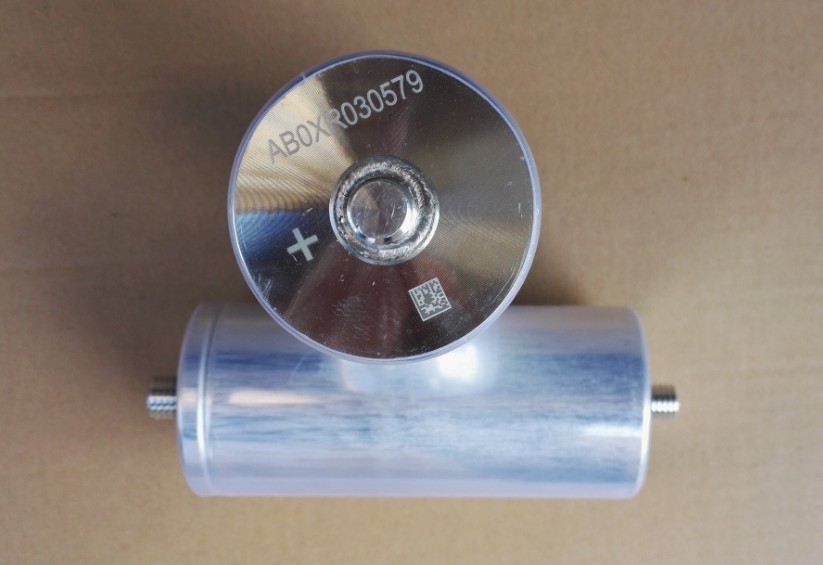
High Temperature Capacitor for Downhole Monitoring of Smart Wells
The objective of production well flow performance and other parameter monitoring is to optimize oil and gas production. The article describes the concept of continuous downhole monitoring of operating well perforation intervals. This can be achieved through the use of a permanent instrument capable of measuring flow parameters (temperature, pressure, water cut, flow rate, etc.) with high resolution. The instruments are attached to the suction pipe of a submerged electric centrifugal pump. The power supply to the instruments and data transmission to the surface is provided by the pump telemetry system (usually included in a standard BHA).
Introduction
Today, the oil and gas sector are actively developing the smart well system. Smart wells are wells that have instruments to monitor parameters in a real time mode. This article will discuss a well survey conducted during well operations, i.e. continuous downhole monitoring aimed at determining the inflow profile in the production well perforation interval [1]. The current method to determine the inflow profile is well logging when it is necessary to shut down the well, recover the BHA, run the wireline logging equipment (comprising numerous instruments), recover the equipment and redeploy the BHA. This operation consists of at least three trips and takes about a week. The logging equipment includes the casing collar and perforation locator, natural rock gamma-ray activity meter (depth positioning basing on GL data), fluid gamma densitometer, pressure and temperature measuring instrument block, and electromagnetic moisture meter. The widely used alternative is smart liner allowing running of fiber-optic measuring systems such as DTS or FBG into the well.
This paper describes a continuous real-time downhole monitoring system that is used to monitor the flow in the well perforation interval and does not require well shutdown or running special logging equipment. The instruments string attached to the electric centrifugal pump is lowered into the borehole. The cheapest and yet very effective system is distributed temperature logging, which allows temperature profile measurement in the wellbore. When completed with acoustic density transmitters and a electromagnetic moisture meter, the system is a powerful tool to determine the flow component profile. The electric centrifugal pump submerged telemetry cables supply power to the instruments and transmit data- equipment already in use and easily integrated into the field automated process control systems.
Relevancy
Decisions on most effective oil and gas field development or well workover depend on accurate determination of the production well inflow profile. The logging allows to:
1. Stabilize the inflow profile
2. Conduct repair and isolation operations to isolate certain intervals.
3. Identify the most perspective producing intervals or cut hazardous water intrution.
4. Identify week or dead intervals that may be intensified in future (acidizing, hydraulic fracturing, etc.) to increase production.
Determination of producing thickness and inflow profiles includes analysis of the inflow intervals and absorptions as well as mandatory assessment of interval flow rates. The inflow and producing interval composition, quantitative assessment of interval flow rates by components in produced water, oil or gas. Determined inflow profiles will allow the set up and distribution of the produced fluid based on the surveyed horizon thickness. Poor well cementation or casing leakage may result in water intrusion into the borehole and reservoir flooding. Since this may damage the structure, a thorough study of the well physical parameters and technical characteristics should be performed before the interval water cut and absorption analysis.
Physics of the Measuring System
The temperature logging system records temperature in a borehole usually connected to the producing reservoir through perforations or filter. When the fields are developed applying field logging methods, a special study of artificial fields in reservoirs intervals, behind-the-casing flow, etc. is required.
Temperature logging is used to:
1. Identify fluid inflow (injection) intervals;
2. Identify behind-the-casing flow;
3. Identify leaking tubing string or casing;
4. Identify top of cement.
5. Identify fracture height, fluid level in the well, perforation intervals, etc.
The average static geothermal gradient is approx. 0.03°C/m but it may vary considerably depending on the rock thermal conductivity and fluids.
The operating well thermogram will show all heat agitations caused by fluid flow in the reservoir and well. When the dynamic processes stops (after well shut down), the well thermal equilibrium occurs.
Adiabatic expansion of fluids and gases passing through porous rocks and throttling lead to thermal effects. Adiabatic expansion of fluids and gases accompanied by a temperature drop has minor impact on temperature fluctuations in the reservoir and downhole due to high rock thermal capacity. Major downhole temperature fluctuations occur during choking. The temperature fluctuation intensity is defined by Joule-Thomson coefficient which is a partial derivative of temperature T and pressure P at constant enthalpy N.

During temperature logging, intervals of fluid inflow into the well are identified based on temperature change relative to geothermal temperature due to the Joule-Thomson throttling effect and calorimetric mixing effect.
Gas expansion in the wellbore inflow interval is accompanied by throttling effect means a negative temperature anomaly occurs. Fluid inflow from the reservoir usually causes heating.
Alternative Solutions
There is a wide range of temperature logging instruments that can be divided into two groups:
Electric:
• Resistance temperature detector;
• Thermocouples
Optical:
• Distributed temperature sensing systems (DTS) that utilize temperature-dependent light (Raman) scattering in multi-mode quartz glass fiber;
• Point-by-point temperature and pressure Brag sensors (FBG) that utilize dependence of interference filter transmission line – Bragg grating on grating deformation caused by thermal expansion or external hydrostatic compression. The single-mode quartz glass fiber, locally heated by optical pulses is used to modulate refracting index (transitions between glass and crystal phases in the heated area) that forms Bragg grating.

Widely used logging tools (NPF Geofizika, NIID-50 Sova, PKF Geotech) are fitted with platinum RTD allowing temperature measurement up to 280°C with resolution up to 0.003°C and accuracy of ±0.1 – 0.5°C. Digital processing can improve the resolution to 0.00015°C through extending the measurement period.
Raman spectroscopy based DTS allow temperature measurements in a notably larger range – up to 700°C but have very low resolution, 0.1°C, while measuring absolute gradients and 0.01°C while measuring relative variations of temperature gradients and accuracy – ±0.1 – 1°C. The sampling resolution is 0.25 to 1m. Point-by-point FBG has resolution up to 0.01°C with approximately the same accuracy of ±0.1°C and a bit lower range, up to 300°C. The drift does not exceed 0.1°C/year. However all fiber-optic systems assme that the cable is installed to the surface through the wellhead HP lubricator and only then connected to the optical recorder. Today downhole DTS or FBG do not exist and are not currently being developed. Due to these issues, the fiber-optic measuring system price is very high as the fiber-optic cable length must cover the entire depth from the wellhead to the surveyed interval despite of the productive interval thickness.
Notwithstanding DTS advantages, such as long-distance measurements and no electric signals or circuits required, DTS with its low resolution is not suitable to achieve most field logging goals. Generally, the use of fiber-optic systems is limited by the well design and requires smart liners supplied by a number of oil service companies as integral solution. The systems need to be envisaged at the well construction stage and cannot be used in already existing wells [2].
Downhole pressure is measured by instruments based on strain-gage (pressure induces rigid sensing element deformation measured), piezoresistance (pressure induces deformation and changes in SOI resistance) and resonance (pressure induces deformation of quartz crystal in alternator circuit) technology. The most accurate and reliable of these are resonance pressure instruments. The maximum measured pressure is 10 to 150 MPa at resolution of 0.01 – 0.00005% of the full scale and accuracy of ± 0.02–0.1% of the full scale. The drift is max. ±0.02 MPa/year. As mentioned above, FBG measures temperature and pressure at the same time, so the maximum pressure is 70 to 150 MPa at resolution of 0.0002 MPa and accuracy of ±0.015 MPa. The optic sensor is much more reliable and the maximum drift is ±0.003 MPa/year.
Electrical media resistance sensors are used for downhole moisture measuring. Generally this limits the water cut operating range to 0-60%. Accuracy is as good as ± 2% for range of 0–30% and ± 5% for range of 30–60% at resolution of 0.03–0.1%. Despite low accuracy, this is sufficient to identify water breakthrough and flooded intervals to be isolated.
Downhole flow measurements are usually performed using turbine flow meters that measure linear flow velocity up to 15-50 m/min with sensitivity of 0.05–0.3 m/min (dynamic range of 300-100), accuracy of ± 2–5% and resolution of 0.1–0.15 m/min. Consequently flow rate is the product of linear flow velocity in the turbine section area.
Proposed Solution
The proposed solution is aimed at well monitoring during operation in case of artificial lifting when electric centrifugal pumps are used. Artificial lifting is widely used in the Eastern Siberia oil and gas fields where reservoir temperature is 90–110°С and pressure reaches 20-30 MPa. Productive reservoir thickness is 10 to 30m and depth is down to 2000-3000m. The artificial lifting BHP is set up to 10-20 MPa to avoid gas liberation from reservoir fluid in the perforation interval. The reservoir fluid is a water-oil emulsion with water content of up to 60% vol. and conservative gas/oil ratio of up to 100m3/t. Fluid flow rate varies considerably but does not exceed 20m3/h. The electric centrifugal pump is located above the perforation interval at the height where the pump discharge pressure (BHP net of water column hydrostatic pressure) ensures optimal head and rate. It is usually 100-200m. Therefore, the pump discharge pressure is below the gas liberation point and there are gas bubbles in the fluid.

Metering and electronic units must be designed to 150°C, 30 MPa. Thus, the most profitable are the following downhole measuring instruments (Fig. 1):
1. Discrete system consisting of the platinum RTD string measuring temperature in the range of 0-150°C with an accuracy of ±0.3°C and resolution of 0.003°С. The sampling resolution for the temperature profile determination depends on the detector spacing and size. Each reading requires min. 16 bit memory.
2. Thermoanemometric (thermoconductive) flow meters included in the same RTD string but more spaced.
3. Point BHP and temperature instrument located at the instrument string bottom end measuring pressure up to 30MPa with an accuracy of ± 0.02% of the full scale (±6 kPa), and a resolution of 0.002% of the full scale (600 Pa). Each reading requires min. 24 bit memory.
4. Turbine flow meter located directly under the electric centrifugal pump with dynamic range of min. 100; upper level depends on the well design.
5. Capacitance moisture meter connected to the flow meter to measure specific moisture content in the range of 0-60% vol. with resolution of 1% and accuracy of ±5%.
6. Vibration density meter connected to the flow meter to measure fluid density in the range of 0.7–2 g/cm3 with resolution of 0.01%, accuracy of 0.1%, as well as viscosity in the range of 1-100cSt
It is obvious that the main data generator in the system is the RTD string. The string consisting of 20-100 instruments installed every 0.5 m covers 10-30m monitoring intervals. For a 1Hz sampling frequency, the data flow is (20 – 60) x 16 bit × 1 Hz = 320 – 960 bps. Therefore, the proposed downhole monitoring system requires communication line capacity of min. 1Kbs. Today submerged telemetry systems utilize both digital (PK Borets and IRZ TEK) and analog cable channels (Electron and ALNAS) (can be integrated directly into the permanent downhole monitoring system) that meet the requirement.
As an option, the downhole monitoring system can be supplemented by wellhead module that comprises temperature and pressure instrument block, flow meter, density meter, moisture meter, etc. Thus, known borehole data, electric centrifugal pump parameters and wellhead data can show the wellbore operation and make it possible to make prompt decisions regarding development. The integrated downhole and wellhead monitoring system is the basis of the smart distributed system to monitor oil and gas well cluster parameters as proposed in the document [3]. It was demonstrated that such systems provide more information and feature higher measurement accuracy with only one accurate flow meter under shared access [4].
The downhole monitoring system equipment and design mainly depend on the well capacity and equipment risks [5]. Temperature logging sets high requirements of the instruments and should independently operate under severe conditions for a long period without the downhole metrological performance degradation. All this necessitates development of special downhole electronic instruments. Special attention should be paid to EEPROM and powerful batteries capable of working in high temperatures. Commercially available flash-drive controllers have poor wipeout block performance that requires high voltage to reset the flash-drive, as they are. actually DC-DС converters. A self-contained power supply is required in case of power loss on the surface just when important readings related to electric centrifugal pump turbine stop are received and recorded. Today high temperature Li-SoCl2 batteries are used with operating temperatures up to 150/165/200°C and capacity of 800/70/15 W/h respectively. Standard 100 W/h NiMh batteries are suitable for up to 120°C temperatures. High-temperature EEPROM microchips have 32Mbps capacity and are suitable for operation in up to 210oC temperature range.
Pressure instruments are not suitable for long-term operations as the rigid sensor melts in high temperatures. When the electric centrifugal pump is to be replaced or inspected, the measuring system should be recovered together with BHA and tested to find any defective instruments to be replaced. SThe self-calibrating system concept provides for redundancy of instruments and measurements analysis to identify and adjust wrong empirical values [6]. Thus it is possible to identify a defective instrument and adjust its parameters.
Conclusion
The Article describes the feasibility of continuous downhole monitoring of operating well perforation intervals using permanent instruments capable to measure flow parameters (temperature, pressure, water cut, flow rate, etc.) with high resolution. The instruments are attached to the suction pipe of a submerged electric centrifugal pump. The power supply of the instruments and data transmission to the surface is provided by the pump telemetry system (usually included in a standard BHA). As an option, the downhole monitoring system can be supplemented by wellhead module that comprises temperature and pressure instrument block, flow meter, density meter, moisture meter, etc. Thus, known borehole data, electric centrifugal pump parameters and wellhead data can show the wellbore operation and make it possible to make prompt geological and engineering decisions.
“Smart” wells need to include one of the downhole monitoring systems proposed in this article.

 Tel:86 0513 65085106 Fax:86 0513 81164838