- Home
- Products
-
- Film Capacitors
- Polyester Film
- High Voltage
- Polypropylene Film
- Paper Film
- Polystyrene film
- Interference Suppression
- High Voltage Pulse/impluse
- AC Voltage
- Electric Power Train
- SMD / Chip
- For Power Electronic
- Electric Railway Signalling
- Capacitive Divider AC
- Polycarbonate Film
- Polyhenylene Sulfide Film
- PTFE Teflon Film
- Polyethylene Naphthalate Film
- Precision Film
-
 Tel:86 0513 65085106 Fax:86 0513 81164838 See more products, please click on the products center > >
- About Us
- News
- Project
- Service
- HR
- Feedback
- Contact Us

Bus DC Link Capacitors Applications
The bus link capacitor is used in DC to AC inverters to decouple the effects of the inductance from the DC voltage source to the power bridge. Figures 1A and 1B show two examples of a typical hard switched pulse width modulated (PWM) inverter that converts DC voltage to a three phase AC voltage. The bus link capacitor provides a low impedance path for the ripple currents associated with a hard switched inverter. The ripple currents are a result of the output inductance of the load, the bus voltage and the PWM frequency of the inverter. Unfortunately the ripple currents have been the primary factor in sizing the electrolytic bus link capacitor.
The bus link capacitor also plays a role in reducing the leakage inductance of the inverter power bridge. Leakage inductance in an inverter power bridge leads to inefficiencies due to the voltage spikes they produce when the power devices are switched on and off at a high rate of dI/dt. If the leakage inductance gets too large, the switching time of the power switches must be increased to keep the voltage spikes from damaging the power devices. Increasing the switching time of the power devices increases the turn on and turn off losses in each of the power switches contributing to more switching losses which manifest themselves in extra heat dissipation in the switching devices. Having a low impedance DC bus is fundamental for an efficient inverter design. The bus link capacitor’s internal ESL and external packaging is a key to reducing leakage inductance in the inverter power bridge.
BUS CAPACITANCE REQUIRED FOR INVERTERS
The first step in sizing capacitors for inverter bus link applications should be to understand how much bus link capacitance is required for a given inverter design. The biggest design limitation for electrolytic capacitors in inverter applications has been the amount of ripple current that the electrolytic capacitor can sustain. This limits the design criteria of the designer to figuring out how many individual capacitors are required for a given design rather than the total amount of capacitance that is required.
For example, let’s say for a given inverter, the bus link capacitor maximum ripple current requirement is 56 Arms. A 5,000uF / 450V electrolytic capacitor typically will only be able to sustain 28 Arms for a given package size. Therefore the designer must use two 5,000uF electrolytic capacitors totaling 10,000uF to meet the required 56 Arms capability. As will be seen further in this paper, 10,000uF is many times more capacitance then is required to meet the design performance for an inverter.
Having an excessive amount of bus link capacitance also presents some safety concerns. Once the inverter is powered down, a large amount of energy is stored in the bus link capacitor and this energy can be depending on the voltage, lethal if touched by an unsuspecting repair person. Most inverter designs with large amounts of capacitance add circuitry to discharge the bus link capacitors in a quick and safe manner upon power down so as not to present a safety concern. This of course adds complexity and cost to an inverter’s overall design.
Film capacitors do cost more per uF than electrolytic capacitors. It will be shown in this paper that the amount of capacitance needed for an inverter bus link capacitor design is much less for a film capacitor than an electrolytic capacitor since the film capacitor is not limited by ripple current rating like the electrolytic capacitor is. This is why when film capacitors are considered as direct uF replacements in an existing inverter design, the film capacitors will look much more expensive if you simply use the same amount of uF for film capacitors as you would with electrolytic capacitors.
600KVA WINDMILL INVERTER DESIGN EXAMPLE
In the following representative example a customer wants to replace a bank of aluminum electrolytic capacitors with dry polypropylene film capacitors for an inverter bus link capacitor used in a 600KVA windmill application. The inverter has an output inductance of 380μH per phase and a nominal DC bus voltage of 680 volts. The switching frequency is 3kHz and the ripple voltage must be controlled to within 1% of the bus voltage. The ambient temperature requirements are 450C - 600C typical for 80% of application life and 850C for 20% of application life.
The present solution uses twelve aluminum electrolytic capacitors arranged in a series-parallel array to meet the voltage and current requirements.
Each discrete aluminum electrolytic capacitor has these ratings:
• Capacitance: 3,300μF
• DC Voltage: 350V
• Peak Voltage: 400V
• Max. Ripple Current at 3kHz: 19.44Arms
• ESR: 20mΩ
• Temperature rating: -250C to +1050C
• Diameter: 63.5mm (2.500”)
• Length:110mm (4.331”)
The 3-series by 4-parallel aluminum electrolytic capacitor bank ratings:
• Each leg contains 3 capacitors in series providing a working voltage rating of: 350Vdc ∗ 3 = 1,050Vdc
• Peak Voltage: 400Vdc ∗ 3 =1,200Vdc
• There are 4 parallel legs providing a ripple current capability of: 19.44 Arms ∗ 4 = 77.8 Arms
• Bank Capacitance of 3-series by 4-parallel legs: (3,300uF / 3) ∗ 4 = 4,400μF
• Bank ESR: (20mΩ ∗ 3) / 4 = 15mΩ
• Bank Length ∗ Width ∗ Height (includes 20mm clearance around case diameter for mounting bracket): 294mm ∗ 221mm ∗ 110mm = 7.15 liters (436.14in3)
The following are two examples of a film capacitor solution for the windmill inverter bus link capacitor application.
First the standard part solution is a standard package UL34 Series Power Polypropylene Film product which have the following specifications:
• Capacitance: 500μF
• DC Voltage: 1,100
• Peak Voltage: 1,320
• Ripple Current at 3kHz: 126Arms at 450C, 74Arms at 850C
• ESR: 1.5mΩ maximum, 0.8-1.0 typical
• ESL: 45nH typical
• Resonant Frequency: 33.55kHz
• Thermal Resistance: 3.480C/Wdissipated
• Diameter: 120mm (4.724”)
• Length:100mm (3.937”)
2-parallel film capacitor bank ratings:
• Bank Capacitance of 2-parallel legs: 1,000μF
• Bank Discrete Capacitors Required: 2
• Bank DC Voltage: 1,100
• Bank Peak Voltage: 1,320
• Bank Ripple Current Capability at 3kHz: 252Arms at 450C, 148Arms at 850C
• Bank ESR: 0.75mΩ maximum, 0.4-0.5 typical
• Bank ESL: 23nH typical
• Bank Resonant Frequency: 33.55kHz
• Bank Length ∗ Width ∗ Height (includes 10mm air spacing between parts): 260mm ∗ 130mm ∗ 100mm = 3.38 liters (206.26in3)
• Bank Dissipated Watts: 52.712 ∗ 0.0005 = 1.39Wdiss
• Bank Temperature Rise from Dissipated Wattage: 1.39Wdissipated ∗ 3.480C/Wdissipated = 4.80C
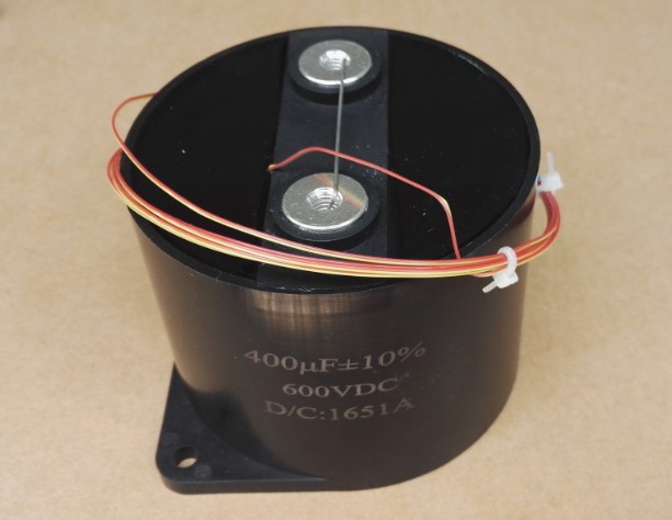
Fig.Fig. 7: Standard Product UL34 Series Power Polypropylene Film
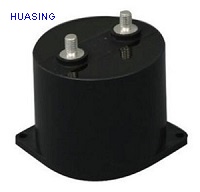
The second film bus link capacitor solution is a UL9 series custom design single package unit with reduced ESR and ESL. A typical package form factor is shown in Figure 8.
Custom UL9 Series film capacitor ratings:
• Capacitance: 1,000μF
• DC Voltage: 1,100
• Peak Voltage: 1,320
• Ripple Current Capability at 3kHz: 252Arms at 450C, 148Arms at 850C
• ESR: 0.75mΩ maximum, 0.4-0.5 typical
• ESL: <20nH typical
• Bank Resonant Frequency: 50.33kHz
• Length ∗ Width ∗ Height: 203mm ∗ 165mm ∗ 89mm = 2.98 liters (182 in3)
• Dissipated Watts: 52.712 ∗ 0.0005 = 1.39Wdiss
• Temperature Rise from Dissipated Wattage: 1.39Wdissipated ∗ 2.520C/Wdissipated = 4.80C
Fig. 8: UL9 Series Custom Design Polypropylene Film Unit with Reduced ESR and ESL.
TABLE 2. WINDMILL INVERTER BUS LINK CAPACITOR BANK PARAMETER COMPARISION
|
Property / Parameter |
UL34 Series Dry Polypropylene Film Discrete Capacitor Bank |
UL9 Series Custom Dry Polypropylene Film
Single Package
|
|
|
Capacitor |
Aluminum Electrolytic Screw Terminal Type, 105oC Standard |
Standard Case Large UL34 Power Film Filter Cap, Threaded Bushing Terminals |
Single UP9 type Power Film Filter Cap Threaded Bushing Terminals |
|
Operating Temp Range |
-250C to +105oC |
-550C to +1050C |
-550C to +1050C |
|
Storage Temp Range |
-250C to +1050C |
-550C to +1050C |
-55oC to +1050C |
|
Capacitor Bank Component Count
|
12 |
2 |
1 |
|
Capacitor Bank Dimensions LxWxH |
294mm x 221mm x 110mm = 7.15 liters |
260mm x 130mm x 100mm = 3.38 liters |
203mm x165mm x 89mm = 2.98 liters |
|
Capacitor Bank Cubic Volume
|
436.14in3 |
206.26in3 |
182.0 in3 |
|
Capacitor Bank Capacitance |
4,400µF +/- 20% |
1,000µF +/- 5% |
1000µF +/- 5% |
|
Capacitance Change vs.Temperature
|
-25.0 % at -250C
-5.0 % at +1050C
|
+2.0 % at -550C
-4.0 % at +1050C
|
+2.0 % at -550C
-4.0 % at +1050C
|
|
Capacitor Bank Minimum Capacitance
Value
|
4400 - 20% - 25% = 2640µF |
1000 - 5% - 4% = 912µF |
1000 - 5% - 4% = 912µF |
|
Capacitor Bank Working Voltage
|
1050vdc |
1100vdc |
1100vdc |
|
Capacitor Bank Surge Voltage (DWV) |
1200vdc |
1320vdc |
1320vdc |
|
Tan δ |
0.20 |
0.0001 |
0.0001 |
|
Capacitor Bank ESR at 3kHz |
15 mΩ typical |
0.75 mΩ maximum, 0.4- 0.5 mΩ typical |
0.75 mΩ maximum, 0.4- 0.5 mΩ typical |
|
Capacitor Bank Resonant Frequency |
|
33.55kHz |
50.33kHz |
|
Capacitor Bank ESL |
|
<23nH |
<20nH |
|
Capacitor Bank Leakage Current (µA) |
6.3 at 1050vdc (1.58 Megohms Insulation Resistance) |
0.20 at 1100vdc (5.00 Megohms Insulation Resistance) |
0.20 at 1100vdc (5.00 Megohms Insulation Resistance) |
|
Ripple Current 450C Ambient 3kHz (Arms) |
77.8 |
252 |
252 |
|
Capacitor Bank Power Density, 3kHz, 450C Ambient ((V*I)/in3) |
187.3watts/ in3 |
1343.9watts/ in3 |
1523.1watts/ in3 |
|
Capacitor Bank Current Density, 3kHz, 450C Ambient (Arms/ in3) |
0.18 |
1.22 |
1.38 |
|
Capacitor Bank Energy Density 450C Ambient (Joules/ in3) |
5.56 |
2.93 |
3.32 |
|
Capacitor Bank Dissipated Watts as
Heating Losses
|
41.69 |
1.39 |
1.39 |
|
Thermal Path |
Aluminum can housing and terminals to bus, internal winding is suspended in can and does not provide good thermal path. |
Terminals to bus and case base in mounting plane (base is electrically isolated), potting compound is doped for heat transfer. |
Terminals to bus and case base in mounting plane (base is electrically isolated), potting compound is doped for heat transfer. |
|
Capacitor Bank Thermal Resistance |
|
3.480C/Wdissipated |
2.520C/Wdissipated |
|
Capacitor Bank Heat Rise from 52.7Arms at 3kHz |
|
ΔT=I2*ESR*(oC/Wdissipated)
=52.712*0.0005*3.48=4.8°C
|
ΔT=I2*ESR*(oC/Wdissipated)
=52.712*0.0005*2.52=3.5°C
|
|
Capacitor Bank Life Expectancy at 850C ambient, 325Vdc bus voltage and full load current rating |
~20,000 hours |
Hot Spot Temp=Ambient
+ ΔT = 85 + 4.8 = ~90°C
>115,000 hours
|
Hot Spot Temp=Ambient
+ ΔT = 85 + 3.5 = ~89°C
>122,000 hours
|
|
Capacitor Bank Weight |
18 lbs. |
9.28 lbs. |
8.55 lbs. |
|
Capacitor Bank F.I.T. (Failures In Time per billion component hours) |
|
At 680Vdc and Hot Spot 0C: 108 F.I.T. at 105°C
38 F.I.T. at 85°C
3 F.I.T. at 45°C
|
At 680Vdc and Hot Spot 0C: 108 F.I.T. at 105°C
38 F.I.T. at85°C
3 F.I.T. at 45°C
|
|
Capacitor Bank End of Life Minimum Capacitance |
Electrolyte dries out causing a large capacitance loss >20%
Note: 2640µF - 20% = 2112µF
|
Electrode wear out for loss of capacitance >10%
Note: 912µF - 10% = 821µF
|
Electrode wear out for loss of capacitance >10%
Note: 912µF - 10% = 821µF
|
|
Packaging Benefits |
Added bracket and cost, outer sleeve is not intended as electrical insulator |
Molded shell has integrated mounting flange, shell is electrical insulator, mounting base conducts to cold plate |
Rectangular case has integrated mounting flange, case is electrical insulator, mounting base conducts to cold
plate
|
|
Approximate Cost
at 1000 Banks
|
(12 x $25) = $300 |
(2 x $98.80) = $197.60 |
$165.68 |
|
$ / uF |
$0.068 |
$0.198 |
$0.166 |
|
$ / Amp 450C |
$3.58 |
$0.78 |
$0.66 |
The cost, volume, weight and efficiency of either of the film solutions presented offer a clear advantage over the aluminum electrolytic capacitor bank. The life expectancy of the film capacitors is at least 5x the aluminum electrolytic capacitors. Considering the labor savings of reduced assembly time and number of connections combined with the minimal bus work required versus the aluminum electrolytic capacitor bank and the savings at a system level is substantial. Field service costs become a fraction of those with the aluminum electrolytic capacitors offering an increased after market value. Additionally the film solutions can have value added functions such as the patented technologies of “Fuseac®” and “Control-cap”. Fuseac® technology employs a series disconnect thermal fuse which will open when the capacitor exceeds 1050C in the hot spot. Control-cap technology uses embedded sensors to provide control signals back for diagnostic alerts or controlled power-down or other system level actions.
Copyright @ 2022HUASING all rights reserved. >> Site Map 