- Home
- Products
-
- Film Capacitors
- Polyester Film
- High Voltage
- Polypropylene Film
- Paper Film
- Polystyrene film
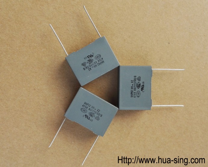
- Interference Suppression
- High Voltage Pulse/impluse
- AC Voltage
- Electric Power Train
- SMD / Chip
- For Power Electronic
- Electric Railway Signalling
- Capacitive Divider AC
- Water Cooled Resonant Capacitor
- Polycarbonate Film
- Polyhenylene Sulfide Film
- PTFE Teflon Film
- Polyethylene Naphthalate Film
- Precision Film
-
 Tel:86 0513 65085106 Fax:86 0513 81164838 See more products, please click on the products center > >
- About Us
- News
- Project
- Service
- HR
- Feedback
- Contact Us


Filter capacitor
2019/2/25 2:45:02
Filter capacitor
A capacitor is two conductors that are close to each other and insulated from each other.
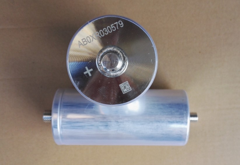
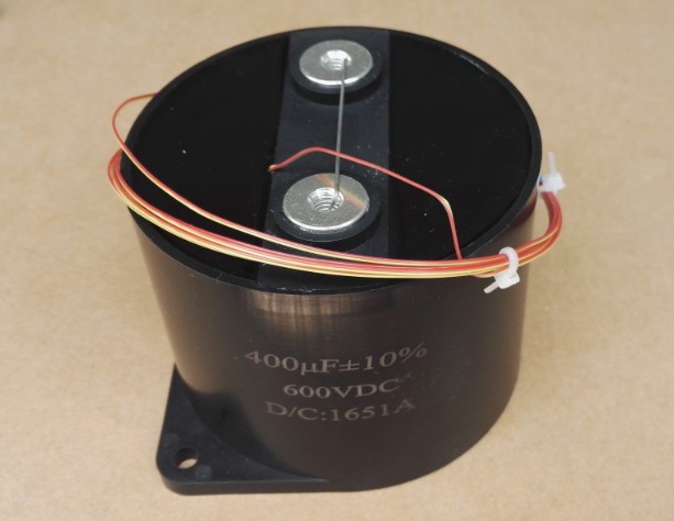
The filter capacitor refers to an energy storage device installed at both ends of the rectifier circuit to reduce the AC ripple ripple coefficient and improve the efficient and smooth DC output. Since the filter circuit requires the storage capacitor to have a large capacitance. Therefore, most filter circuits use electrolytic capacitors. Electrolytic capacitors are named for their use of electrolytes as electrodes (negative electrodes).
Function
The filter capacitor is used in the power rectifier circuit to filter out AC components. Make the output DC smoother. Moreover, for precision circuits, this time, a combination of parallel capacitor circuits is often used to improve the working effect of the filter capacitors.
The low-frequency filter capacitor is mainly used for filtering after mains filter or transformer rectification, and its working frequency is 50Hz consistent with the mains; the high-frequency filter capacitor mainly works after the rectification of the switching power supply, and its working frequency is several thousand Hz to several Ten thousand Hz. The filter capacitor plays a very important role in the switching power supply. How to correctly select the filter capacitor, especially the selection of the output filter capacitor is a problem that every engineering technician is very concerned about.
A common electrolytic capacitor used in a 50 Hz power frequency circuit has a ripple voltage frequency of only 100 Hz and a charge and discharge time of the order of milliseconds. In order to obtain a smaller pulsation coefficient, the required capacitance is as high as several hundred thousand microfarads. Therefore, the goal of ordinary low frequency aluminum electrolytic capacitors is to increase the capacitance, and the capacitance, loss tangent and leakage current of the capacitor are identified. The main parameters of its pros and cons. The output filter electrolytic capacitor in the switching power supply has a sawtooth voltage frequency of up to tens of thousands of Hertz, or even tens of megahertz. At this time, the capacity is not the main indicator. The standard for measuring the advantages and disadvantages of high-frequency aluminum electrolytic capacitors is the "impedance-frequency" characteristic. It is required to have a lower equivalent impedance in the operating frequency of the switching power supply, and at the same time, it has a good filtering effect on the high frequency spike signal generated when the semiconductor device operates.
Ordinary low-frequency electrolytic capacitors begin to exhibit inductivity around 10,000 Hz, which cannot meet the requirements of switching power supplies. The high-frequency aluminum electrolytic capacitor dedicated to the switching power supply has four terminals, and the two ends of the positive electrode aluminum piece are respectively taken out as the positive electrode of the capacitor, and the two ends of the negative electrode aluminum piece are also taken out as the negative electrode. The current flows from one positive end of the four-terminal capacitor, through the inside of the capacitor, and from the other positive end to the load; the current returning from the load also flows from one negative end of the capacitor to the negative end of the power supply from the other negative end [3 ].
Classification
In general, the function of the electrolytic capacitor is to filter out low-frequency signals in the current, but even for low-frequency signals, the frequency is divided into several orders of magnitude. Therefore, in order to be suitable for use at different frequencies, electrolytic capacitors are also divided into high frequency capacitors and low frequency capacitors (the high frequencies here are relative):
(1) The low-frequency filter capacitor is mainly used for filtering after mains filter or transformer rectification, and its working frequency and mains are consistently 50Hz.
(2) The high-frequency filter capacitor mainly works after the rectification of the switching power supply, and its working frequency is several thousand Hz to several tens of Hz.
Characteristics
Low temperature rise
The harmonic filter circuit consists of a capacitor series reactor, which forms the lowest impedance at a certain harmonic order to absorb a large amount of harmonic current. The quality of the capacitor will affect the stable absorption effect of the harmonic filter. The temperature has a great relationship. The higher the temperature, the lower the life. The filter full-film capacitor has the characteristics of low temperature rise and can guarantee its service life.
Low loss
Dielectric loss tangent (tgδ): ≤ 0.0003.
Safety
It complies with GB and IEC standards, and the internal single capacitors are equipped with protection devices; when the line or single capacitor is abnormal, the protection device will immediately operate and automatically cut off the power supply to prevent secondary disasters. A discharge resistor is included to ensure safe use of electricity and maintenance. The outer casing is stamped from steel plate, and the interior and exterior are coated with high-temperature paint with good weather resistance.
Convenience
Small size and light weight, easy to handle and install
Two points about capacitive filtering are careful to introduce ground interference to the device.
Two points of capacitance filtering
Capacitors are very important in EMC design, and they are also commonly used filter components! But in the course of my training, I found that the use of capacitors is not very clear! Here I introduce two points of capacitance filtering:
1, capacitor filtering is a frequency band, many people think that the larger the capacitor, the better, in fact, each capacitor has a certain filter frequency band, large capacitor filter low frequency, small capacitor filter high frequency, mainly based on the resonant frequency of the capacitor It is decided that the capacitor has the best filtering effect at the resonance frequency point! There is a good filtering effect in a frequency band centered on the resonance point, and the filtering effect of other parts is not good! The resonance point of the capacitor is related to the capacitance of the capacitor and ESL (equivalent series inductance). You can check the online information and the theoretical analysis of the series resonant circuit in the conference school. Usually we recommend adding a UF-level capacitor to the power port to filter differential mode interference between a few hundred KHZ and 5MHZ, because the UF-level capacitor resonance point is around 1 MHz. In addition, it is recommended to add 1nF chip capacitor on the high-frequency digital circuit. The reason is that the resonant frequency of 1nf capacitor is between 100MHZ. The resonance frequency of different manufacturers is different, so it is better to filter tens of MHZ to 200MHZ interference. Solve problems with EMI!
2, the capacitor is selected, it does not mean that it can filter out interference! When the river is flooded and reaches a high water level, we will often increase the drainage of a ditch. The place to be led must be a low water level. If it is led to a high water level reservoir, it will cause water to be poured and raise the water level. Capacitor filtering is the same as the problem of water management. The capacitor only acts as a ditch. Whether it can be filtered depends on the size of the ground interference connected to the capacitor. We often find that engineers solve the interference problem and the capacitor has no effect. To a large extent, the ground interference itself is very large! Instead, bring the ground interference to the signal or power supply! Everyone needs to be aware that the ground disturbance is not the smallest in some cases! Therefore, we emphasize that there is an important basis for filtering, that is, the ground to be connected is small, which is usually called "quiet ground".
Therefore, when we adopt capacitive filtering, we must achieve the filtering effect. We must select the appropriate capacitor and the ground with less interference! Capacitors can be based on the device manual and experience. If the interference is small, the instrument can be used during debugging. Experienced engineers should consider the previous schematic and PCB.
Friend Link:
Alibaba Store
Copyright @ 2024HUASING all rights reserved. >> Site Map 