- Home
- Products
-
- Film Capacitors
- Polyester Film
- High Voltage
- Polypropylene Film
- Paper Film
- Polystyrene film
- Interference Suppression
- High Voltage Pulse/impluse
- AC Voltage
- Electric Power Train
- SMD / Chip
- For Power Electronic
- Electric Railway Signalling
- Capacitive Divider AC
- Water Cooled Resonant Capacitor
- Polycarbonate Film
- Polyhenylene Sulfide Film
- PTFE Teflon Film
- Polyethylene Naphthalate Film
- Precision Film
-
 Tel:86 0513 65085106 Fax:86 0513 81164838 See more products, please click on the products center > >
- About Us
- News
- Project
- Service
- HR
- Feedback
- Contact Us


Inverter DC Link Capacitor Selection
2020/11/4 3:18:34
Properly dimensioning the DC link capacitor for a three phase inverter seems to be a skill that evades a lot of power electronic engineers. When I ask people how they size their DC link capacitor, it’s usually based off some arbitrary rules-of-thumb or back-of-the-envelope calculations. I find that crazy, especially since the DC link capacitors can occupy 20-50% of the total inverter volume. With electric vehicles, inverters are typically optimized for two things - power density and efficiency. Thus, DC link should not be any larger than what the requirements call for. The objective of this article is to help you better understand the role of the DC link capacitor and how to properly size it based off your requirements.
DC LINK CAPACITOR ROLE
Figure 1 shows a simplified circuit diagram of a typical electric vehicle traction system - AC motor driven by a two-level, three-phase Voltage Source Inverter (VSI) connected to a battery. The inverter’s job is to synthesize three sinusoidal current waveforms to drive an AC motor. S1-S6 are switched on and off thousands of time per second using a Pulse Width Modulation (PWM) strategy to create effective output voltages that vary sinusoidal in time. The phase current tracks with the phase voltages based on the resistance and inductance of the motor.
![Figure 1: Simplified Inverter Circuit Diagram [1]](/pic/other/2020-11-04-21-46-238.jpg)
Figure 1: Simplified Inverter Circuit Diagram [1]
In a VSI, the DC link capacitor has two main responsibilities –
1.Provide low impedance path for high frequency currents – As frequency goes up, the battery and cable parasitic inductance cause the impedance to increase. The DC link capacitor impedance goes down so it becomes the preferable path for high frequency AC to circulate. We call this ripple current.
2. Stiffen the DC bus - Decouple the effects of stray inductance from the DC voltage source to the power bridge. Voltage ripple on the DC bus will show up as ripple in the phase current which is undesirable so its important to have a stiff DC bus. You should have a specification that defines the maximum allowable ripple voltage on the DC bus. This spec is used to calculate the capacitance required.
When sizing a DC link capacitor for inverter applications, the ripple current requirement typically ends up being the limiting factor [1] [2] and drives which capacitor is selected. Ripple current, in this context, is referring to the AC current the capacitor must supply to the power bridges and the motor.
Film or Electrolytic Capacitor?
Because, the ripple current ends up being the driving requirement, most modern inverters use film capacitors. Compared to electrolytics, film caps have high ripple current rating due to their low ESR and ESL. Electrolytics have a higher capacitance/volume ratio than film caps, but the ESR and ESL is much higher so you need to put many of them in parallel in order to satisfy the ripple current requirement. The volumetric efficiency typically ends up being much higher if film capacitors are used. Additionally, the working lifetime rating of electrolytics is around 10k hours, whereas for film it’s 100k hours [1]. This is because the electrolyte dries out and leads to increased ESR which increases power loss and ultimately results in failure. There is a lot to be said about the advantages of film caps over electrolytics, but I don’t want to digress too much into that and convolute the post. To read more, you can check out [2].
RIPPLE CURRENT REQUIREMENT
Before I start, I must preface this by saying, this analytical method for ripple current calculation is only applicable for inverters using Space Vector Modulation (SVM). If other PWM strategies are used, you may want to perform a spectral decomposition of the DC link current. See [5].
Background/Theory
OK. Let’s get into it. The inverter input current, i, is composed of both AC and DC components
Equation (1)
To solve for the RMS value of the inverter input current, we can use the following equation -
Equation (2)
As stated above, as frequency increase, battery impedance goes up and capacitor impedance goes down so it becomes the preferable path for high frequency AC to circulate. We can assume the battery supplies purely DC current and the capacitor must supply all the AC. This includes the AC components of the fundamental, harmonics, and the current ripple at the switching frequency.
Equation (3)
We can solve for the RMS value of the capacitor current -
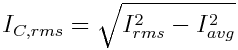
Equation (4)
Ok great. Now we just need to find the inverter RMS and average value current, then we can solve the capacitor RMS current. Johann Kolar from ETH Zurich did some fantastic work on deriving these equations analytically closed form in the time domain. We aren’t going to go through that here, but if you are interested in the derivation, see [3]. The equations for RMS current and average inverter input current are shown below -
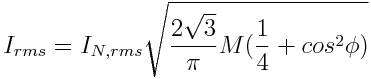
Equation (5)
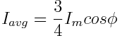
Equation (6)
Using these two equations, we can now synthesize a closed form solution for the capacitor RMS current -
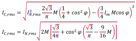
Equation (7) and (8)
We can see that the capacitor current is dependent on the phase current, modulation index, and power factor. If we plot capacitor current normalized to phase current vs. modulation index for several different power factors, we get the following plot -
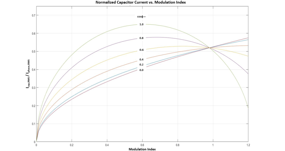
Figure 2: Capacitor current normalized to phase current vs modulation index for power factors from 0 - 1.0
Most Permanent Magnet (PM) motors have power factors in the range of 0.70 - 0.95 [4] so you can see from the plot above that maximum capacitor current in this power factor range occurs when the modulation index is somewhere between 0.6-0.75. The capacitor current will be 0.55-0.65 x the phase current for PM motors with these power factors.
RIPPLE VOLTAGE REQUIREMENT
The second role of the DC Link capacitor is to smooth DC voltage fluctuations and “stiffen” the DC bus. This is important because any voltage ripple on the DC bus shows up as current ripple in the phase currents, and that leads to torque ripple. Not good. Ultimately, you should have a specification for the maximum allowable voltage ripple on the DC bus under certain conditions (typically worst case - full load, 50% SOC, etc.). Usually, this number ranges from 1-10%. It depends on maximum allowable torque ripple. That’s where the spec comes from.
Rearranging the equation, we can solve for capacitance.
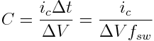
Equation (10)
We can see that there is diminishing return on bus voltage ripple after a certain amount of bus link capacitance due to the 1/C relationship. Beyond a certain point, adding capacitance does little to improve inverter performance.
Figure 3: DC bus voltage ripple peak-to-peak vs. Capacitance
We can also see from Equation (10) that capacitance is inversely proportional to switching frequency. As fsw increases, the capacitance required decreases. Capacitor volume is proportional to capacitance so if you increase switching frequency, higher power densities can be achieved.
This is one of the reasons why SiC and GaN-based converters can achieve higher power densities than IGBT-based converters.
Switch faster -> less capacitance required -> volume decreases -> higher kW/L and kW/kg.
DIMENSIONING THE CAPACITOR
Ripple Current Rating
The ripple current rating of a capacitor is derived from its thermals. Its dependent on the ESR (loss mechanism) and the thermal resistance. As the capacitors go through charge-discharge cycles at high frequency, the conductors inside get hot and raise the internal temperature of the capacitor. It is necessary to limit the temperature rise so that the capacitor does not deteriorate. The manufacturer will typically specify the maximum RMS ripple current rating at an ambient temperature that you must not exceed to guarantee the lifetime rating of the capacitor.
It's good to be conservative so select a capacitor with a ripple current rating that is 1.1x or higher than your worst case ripple current. With that said.. because this is a thermal rating, you could rate it based on the time average phase current based on your load cycle.. if you are really trying to optimize for power density.
DC Voltage Rating
In general, the DC voltage rating of the capacitor should be rated based on the average maximum bus voltage x 1.1 (factor of safety) . E.g. if your 100% SOC battery voltage is 400V, the voltage rating of the capacitor should be 450V or higher.
The factor of safety can be relatively low for the voltage rating because film capacitors can withstand a DC potential of 1.3 x rated voltage for one minute without damage or breakdown. So a 450V capacitor can actually withstand 585V for a minute.
If you are driving a PM motor that can operate in the flux weakening region, then you will want to rate the DC bus link capacitor voltage based on the back emf that can be generated at the maximum speed of the motor. Energy balance equation can be used to solve for this.
Resonant Frequency Rating
Because the capacitor has ESL, there is a frequency at which the capacitor self-resonates. Beyond this point, the capacitor, the capacitor behaves as an inductor and it does no good. With that said, the capacitor you select should have a resonant frequency 2x higher than your switching frequency [6]. So if you switch at 100kHz, you should have at least 200kHz rated caps. This warrants investigation using PCB mount MLCC capacitors, but that’s for another article. This is a very important to keep in mind for SiC or Gan based-inverters, but if you are switching at 20kHz, its less of a concern.
Capacitance Rating
As stated above, there is typically some slack with this requirement.. That is, the capacitance required for power inverter applications usually is not much. Most state-of-the-art inverters don’t have more than 2000uF. That’s because you get diminishing returns in performance past a certain point as shown in Figure 3.
With that said, select your capacitor(s) based on the ripple current, bus voltage, resonant frequency, packaging, and cost constraints. Check analytically and run simulation to ensure that the capacitance meets the DC bus voltage ripple requirements.
Capacitance, ESR (ripple current rating), insulation resistance, and voltage rating are temperature dependent parameters so make sure to factor this in when dimensioning your capacitor.
Make sure that you can place your capacitor as close to the terminals of your semiconductors as possible. If there is significant loop inductance between the DC bus link capacitors and the semiconductor switches due to packaging, you may want to consider adding low uF snubber capacitor to filter out high frequency currents.
SIMULATION
After I do analytical calculations, I like to run circuit simulation to double check my work. My electric powertrain schematic is shown below.
· Simulation parameters are shown in the tabIe on the left
· Simulation was run for worst case conditions - base speed, full load operation.
· The battery, cable, and DC link capacitor parasitics are included in the model.
· Using full centered space vector modulation pwm scheme
I have correlated real experimental data with my simulation model so I know it’s for the most part correct.
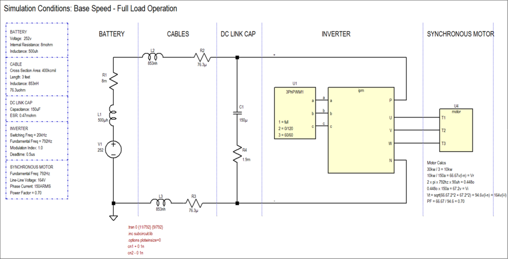 Figure 4: Simulation schematic of EV traction system that I use for dimensioning capacitors. Includes parasitics of battery, cable, and dc link capacitor. Component parameters on the left.
The battery current, phase currents, and capacitor current is shown below.
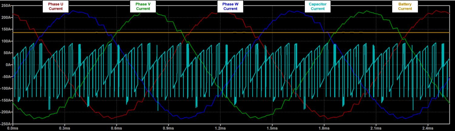
Figure 5: Plot of phase currents, battery current, and capacitor current. Simulation was ran at base speed - full load conditions with a modulation index of 1. Battery current is entirely DC and capacitor is AC
Simulations were ran for full load at 1/4, 1/2, 3/4, and full output frequency. The following currents and voltage ripple were measured -
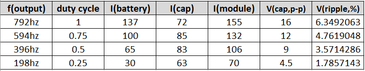
Measured currents and voltage ripple for simulation at full load for 1/4, 1/2, 3/4, and full output frequency
The battery current shows a linear relationship to duty cycle. The inverter module current shows a square root relationship. The capacitor current is the RMS difference between the two.
· I(mod) = 155 * sqrt(duty)
· I(bat) = 137 * duty
· I(cap) = sqrt(I(mod)^2 - I(bat)^2)
Using these relationships, we can approximate the currents at all modulation indexes from 0 to 1. The plot below shows the results for capacitor current vs modulation index.
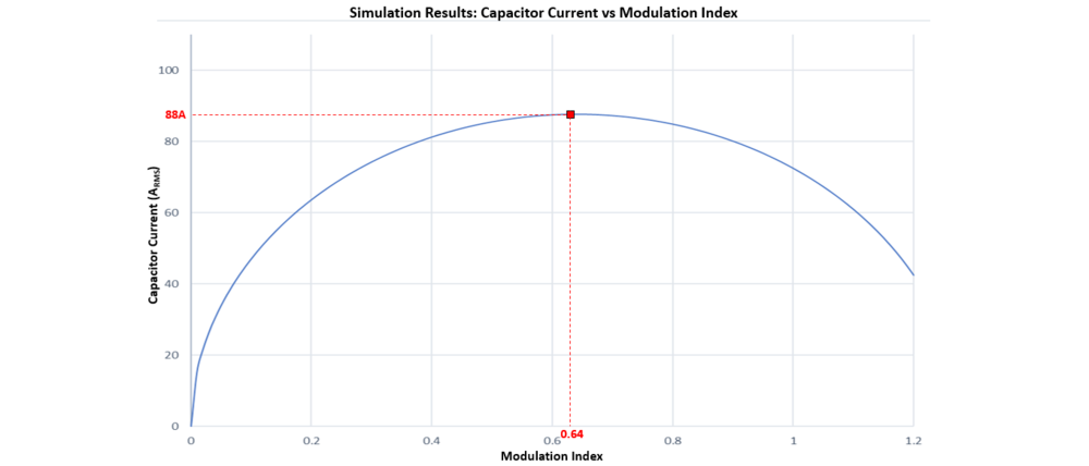
Figure 6:
As you can see from the plot above, the maximum capacitor RMS current is 88A (0.57x phase current) and it occurs at a modulation index of 0.64. Our analytical calculations state that capacitor current should be ~85A at this power factor and modulation index.
The results of the analytical calculation are within 3% of measurements made from the circuit simulation. Not bad!
To review, we first covered the role of the inverter within the traction system and the role of the DC link capacitor. Then, we looked at how to determine the analytical closed form solution for ripple current and ripple voltage using Kolar’s derivation. Based on these requirements along with several others (DC voltage, packaging, etc/), we discussed how to dimension the capacitor. Last, simulation was used to validate our analytical solution for ripple current and ripple voltage.
This article isn’t meant to be an be-all-end-all guide to selecting a DC link capacitor. There are just too many application dependent things to consider. But it should help you get started in the right direction.
You can choose suitable specification from here: http://hua-sing.com/eproducts/Metallized-Polypropylene-Film-DC-Link-Capacitor-127.html
Of course, you can email us sales@hua-sing.com if have any query.
References
[1] https://www.ecicaps.com/tech-tools/technical-papers/low-inductance-dc-bus-capacitor-high-power-traction-motor-drive-inverters/
[2] https://www.kalbeck.com/asset/630/Whitepaper%20SalconeBond.pdf
[3] http://citeseerx.ist.psu.edu/viewdoc/download?doi=10.1.1.483.1080&rep=rep1&type=pdf
[4] Max’s brain
[5] https://ieeexplore.ieee.org/document/5166465
[6] Recommendation from ECI Caps App Engineer
Friend Link:
Alibaba Store
Copyright @ 2024HUASING all rights reserved. >> Site Map 