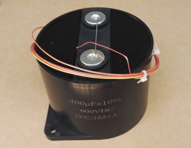
Types of Wound Film Capacitors
2020/11/10 21:52:44
A description of the various types of wound film capacitors available including construction, materials, features, strengths and application information.
Types of Wound Film Capacitors
A Capacitor is passive electronic device, second in use only to that of a resistor. Capacitors can be found in virtually all electronic devices. Simply put, a capacitor is two electrodes (conductors) separated by a dielectric
(insulator).
In this case, the insulator would be air, and the electrode could be any conductive material, such as aluminum or copper. When a voltage potential is applied to the electrodes, an electric field is present in the dielectric, which
in turn stores energy. The measured amount of stored energy is the capacitance. The amount of capacitance is directly proportional to the area of the electrodes, and inversely proportional to the distance between the electrodes. The capacitance is also proportional to the dielectric constant (k) of the insulator, whereas air is 1.00 and polyester is 3.2, therefore at the same distance between the plates, polyester would have 3.2x the
capacitance. The higher the “k” of a particular dielectric, the higher the capacitance for the same given area and distance between the electrodes
Capacitors can be categorized into two different groups, variable capacitors and fixed capacitors. Capacitors are also classified by the type of dielectric used, such as air, vacuum, glass, ceramic, mica, electrolytic, and film. The
largest market share is compromised of three basic groups – Ceramic, Electrolytic, and Plastic Capacitors.
Plastic capacitor (polymer) group consists of three different construction techniques. Wound film, Multilayer (PML), and Stacked film. Wound film includes polymers, paper and paper/plastic, with either metalized electrodes
or discrete foil.
A wound film Capacitor is just that, where two or more films/electrodes are spirally wound on a mandrel to a predetermined number of turns, length, or capacitance value. The mandrel is then ejected from the winding, which is
then further processed depending on the style and/or application of that particular part. Wound Film Capacitors can be further broke down into three basic categories:
Metalized Electrode
Discrete Foil Electrode
Hybrid electrode
Metalized Electrode Capacitor or commonly know as Metalized Film Capacitor, consists of a thin layer of metal, typically aluminum, zinc, or an alloy of aluminum/zinc, which has been previously deposited onto the dielectric. The metal is vacuum deposited onto a master roll of film typically using resistive evaporation (aluminum) or heated crucibles (zinc). Special masking, either mechanical or print transfer is used to make the unmetalized margins. The master roll is then slit into narrower “bobbins” which are used on specialized “winders” to manufacture the wound film capacitors.
The metalization thickness is typically around 200 Ä (Angstroms) or .0000008” thick. When compared to a discrete foil of .00022” thick, the volumetric efficiency (energy density) of a metalized electrode is far greater than that of a discrete foil. Ancillary vacuum technologies exist that allow designed variations of the metalized surface for specific applications. For example, a heavy region is possible where the termination will be attached, thus allowing for higher current capabilities. It is also possible to print patterns onto the dielectric surface, giving specific metal patterns. These patterns are used for high stress and/or high energy applications.
Another major energy density advantage of a metalized electrode is the ability of the film to “self heal” or “clear”. That is, when the voltage is sufficient to break down the dielectric so that there is a direct conducting path from electrode to electrode, (effectively shorting the plates) a small portion of the stored energy in the capacitor discharges into the “short” and creates a super heated area, thus vaporizing the metal away from the break down (pin hole), giving a “clearing site” or margin area without metal. This phenomenon allows for higher stress to the dielectric without failure. A similarly rated discrete film/foil unit would be 2x to 3x larger than the metalized film counter part.
Discrete Foil Electrode is typically aluminum or tin with a thickness around .00022”. The disadvantage of a discrete foil is size, other than the obvious greater electrode thickness, discrete foil capacitors generally require greater
dielectric thickness than their metalized counter part. The primary reason is, if the voltage is sufficient to break down the dielectric, the discrete foil capacitor does not have the ability to self heal, thus it shorts out. Therefore, the design generally has a thicker dielectric to reduce the possibility of shorts. There are, however, some advantages, such as higher current carrying capabilities, Lower Equivalent Series Resistance (ESR) & Equivalent Series Inductance (ESL), and lower losses in general. Discrete foil is also typically used in very low capacitance units where the termination and lead configuration typically govern the size and where the cost of the material is insignificant.
Hybrid Electrode is generally a combination of a discrete foil and a metalized electrode. This configuration is typically employed where a high in-rush current is present and a metalized electrode by itself is not capable of supporting the current, yet the voltage stress requires self healing. The Hybrid electrode combination can also be used where a lower ESR or ESL is necessary, yet a higher energy density is required, that a discrete foil can not offer.
Dielectric or Insulator used in wound capacitors consists of many different materials, all with unique characteristics, which should be considered when selecting a capacitor for a particular application. Typical dielectrics are:
Polyester (Polyethylene Terephthalate) – Mylar*
Polypropylene (OPP or BOPP)
Polycarbonate
Polystyrene
Polyimide – Kapton*
PTFE (Polytetrafluoroethylene) – Teflon*
PPS (Polyphenylene Sulfide)
PEN (Polyethylene Naphthalate)
Paper
Polyester Capacitors or Mylar* Capacitors are one of the most widely used film capacitors. Capacitor grade Polyester film is available in a wide variety of thicknesses, ranging from 0.5 um up to 20 um. Combining the thin film with the relatively high dielectric constant (k) of 3.2, high energy densities are possible. However, Polyester is considered a high loss film and typically not used in applications that require high current or high frequency.
Polypropylene Capacitors are second in use only to Polyester. Capacitor grade Polypropylene is available in thicknesses ranging from 3 um to 15 um.The electrical characteristics of Polypropylene film exhibits many advantages, such as high break down strength, low moisture absorption, low loss factors, and capacitance stability throughout the temperature range. It is ideally suited for high frequency and/or high current applications. The disadvantages of Polypropylene are the relatively low dielectric constant (k) of 2.2 and low maximum temperature of 105 C.
Polycarbonate Capacitors are typically found in high temperature low loss applications. Polycarbonate exhibits good electrical characteristics over the entire temperature range of -65 to +125 C. The dielectric constant (k) of 2.7 is between Polyester and Polypropylene, so energy density is average. Many
military specification capacitors require the use of polycarbonate as the dielectric. Polycarbonate has a questionable availability, so contact the factory with any requirements.
Polystyrene Capacitors exhibit extremely low loss, and excellent electrical characteristics, specifically capacitance change over temperature, which is typically +-1% over the temperature range of -55 to 85 C. Polystyrene has a very low dielectric constant (k) of 2.1, so it is suited for low capacitance applications. Like Polycarbonate film, polystyrene also has a questionable availability, so contact the factor with any requirements.
Polyimide or Kapton* Capacitors are typically used in extremely high temperature applications, up to 250 C. The electrical characteristics are average, and the dielectric constant (k) of 3.4 is close to that of Polyester. Typically, polyimide as a capacitor dielectric is typically combined with a discrete foil. Metalized Polyimide is possible, however it exhibits extremely poor self healing characteristics. The chemistry of the film is such that when a clearing occurs, traces of carbon remain in the area, thus causing tracing and poor electrical properties.
PTFE or Teflon* Capacitors are also used in high temperature applications, up to 200 C. The electrical characteristics of PTFE are excellent, low loss, with high stability; however, cost is very prohibitive. The dielectric constant (k) is very low, around 2.1, so it lends towards low capacitance values. PTFE as a dielectric is typically paired with a discrete foil, as the naturally low surface energy of the film is very difficult to metalize.
PPS Capacitors in some instances can be used as a suitable replacement for polycarbonate capacitors. The material exhibits similar, and in some cases better characteristics than that of Polycarbonate. The available thicknesses are similar to Polycarbonate and due to the higher break down strength and
similar dielectric constant (k), generally replacement size is not a concern. Although PPS is touted as “the polycarbonate replacement” some key manufacturing limitations are present. PPS is not an easily “clearable” film. When used with a metalized electrode, the self healing characteristic tends to leave small traces of carbon, which in turn, exhibits slightly higher insulation resistance than it’s polycarbonate counter part.
Paper Capacitors are old technology, however are still widely used in high voltage and high power applications. Paper, as a dielectric, requires impregnation to enhance the electrical properties of the paper, thus making it suitable for high voltage capacitor applications. The oil suppresses the corona phenomenon, which if allowed to exist, will degrade the dielectric, leading to eventual failure. Paper can be combined with Polyester or Polypropylene to obtain different characteristics, such as lower loss, or high dielectric withstand. The dielectric constant (k) of paper is highly debated subject however, the actual K of paper is primarily dependant on the impregnants used during manufacturing.
Capacitor Types and/or Styles can be reduced into two different categories, Non-hermetically Sealed and Hermetically Sealed. Each category can be further reduced into many sub-categories depending on specific application or costs associated with the capacitor.
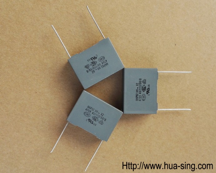
Non-Hermetically Sealed Capacitors are typically packaged in a nonmetallic housing or enclosure, such as tape wrap and epoxy endfill or a preformed epoxy case. This style offers basic environmental protection, however, costs are minimal. The three primary types of non-hermetics are Wrap & Fills, preform case, and bare windings. Wrap & Fills (W & F) are probably the most common film capacitor configuration. It offers adequate environmental protection, and is extremely cost effective. W & F’s are typically packaged either as a round or flatten part. The flatten configuration is used where a space constraint is an issue. The construction of a wrap & fill, is precisely that, the capacitor element (winding) is wrapped with a 1 – 2mil thick tape, slightly wider that the winding, then the ends are filled with a suitable epoxy. Preformed cases come in a multitude of configurations ranging from radial rectangular, axial rectangular, to cylindrical with screw studs. The case material make-up ranges from molded epoxies, to injection molded polymers. This style typically offers great environmental protect than that of a wrap & fill. After the capacitor winding is inserted into the case, the case is typically back-filled with an epoxy. Bare Winding (capacitor section) is typically supplied to another manufacturer or OEM, which uses the winding as part of an assembly. The assemblies range from audio capacitors with specific form/fit requirements, to EMI Filter or RFI filter assemblies. Bare windings can be a film/foil which can be terminated into a feed-thru assembly via compression or and endsprayed metalized winding that is ready to accept soldering.
Hermetically Sealed Capacitors are typically supplied for severe or extreme environmental conditions or in the case of an oil filled capacitor, to contain the oil. Conditions include high humidity, corrosive, or particulate contamination. Hermetically Sealed configurations can be further reduced into three Categories:
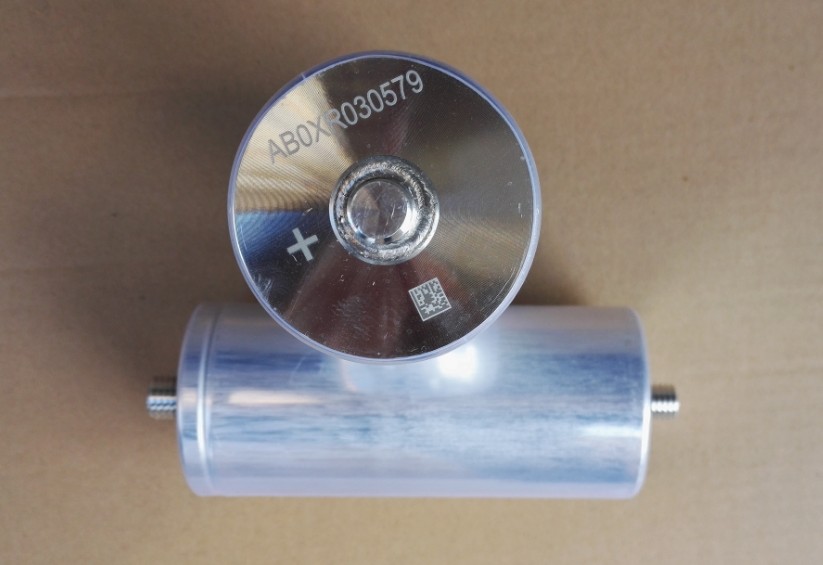
Tubular Capacitors are typically axial, whereas, the lead termination is along the center axis of the device. The tubular configuration offers size advantaged over rectangular, the capacitor sections are normally round and fit efficiently into a tubular enclosure. However, the capacitance is generally low due to the size limitation of the tubular enclosures. Tubular configuration can be further broke down into two additional categories metal and non-metallic.
Metal tubular capacitors generally use a non-ferrous tube, sealed on one or both end with a glass-to-metal seal. This configuration is typically used in low voltage applications (>1000 V), due to lack of adequate space for insulation between the capacitor section and the case. This style can be configured
with various mounting options, such as wrap around brackets or threaded mounts. Optional lead terminations are available, ranging from solid wire to solder lugs.
Non-metallic (glass or ceramic) tubular capacitors are general used for high voltage applications. The tube is an insulator, therefore does not require additional insulation between the capacitor section and the enclosure. The tube is supplied with metalized bands around the outside of the ends to solder metal caps onto. Terminations are typically wire leads or threaded studs.
Rectangular Capacitor configurations are generally used for higher capacitance values and or high voltage. Typically rectangular style enclosures required multiple flatten sections to conform to the rectangular shape. Rectangular configuration can be further reduced into to three additional categories.
Drawn enclosures sizes are numerous, but fixed by the various manufacturers available tooling. They are formed using dies on large presses, from a single piece of material, either ferrous or non-ferrous.This construction is strong and cost less than the fabricated style enclosures. The lids can be either inside or outside fitting depending on the specific customer requirement. Terminations are typically installed on the enclosure lid, and range from Glass-to-metal lugs to high voltage ceramic busing with studs. The lids and terminations are typically soft solder onto the lid/enclosure. The enclosure can be
fitting with mounting brackets per the customer’s requirements.
Fabricated enclosures have limitless size range, whereas, they are manufactured per order. They exhibit the same characteristics of the drawn counter parts, with a few exceptions. The fabrication process requires more effort, therefore the costs are typically much higher. Due to the nature of the construction, welded seams, they are inherently weaker than a similar sized drawn enclosure. All other aspects are the same as the drawn units.
Fabricated Welded enclosures are generally large, where one of more of the dimensions is several inches or more. They are typically manufactured from mild steel or stainless steel construction, with material thicknesses between .040” and .109”. These enclosures are typically used for high voltage applications where the use of oil is necessary. The lids are typically welded on, prior to impregnation, using a TiG welder. The enclosures are then painted with a two part epoxy paint for corrosion resistance. Mounting brackets can be incorporated into the design, to facilitate easy mounting.
Double rolled Seam enclosures or DRS, are similar to drawn, except the lid is not soldered, but rolled into a seam giving a “hermetic like” seal. The “sealing” process is fast and very effective, using a sealant and a mechanical seam to create the seal. The available sizes are fixed, somewhere around a dozen base sizes. The height generally can be ordered in a wide range of size, in 1/16” increments. DRS enclosures are available in three basic shapes, rectangular, oval, and round. The oval and round configurations are typically used for motor capacitors. They can be fitted with a variety of terminations ranging
from solder lugs to high voltage ceramic bushing with screw terminations.
CAPACITOR APPLICATIONS
HUASING Capacitors manufactures a broad spectrum of reliable wound film capacitors suitable for a wide variety of applications. Many of the catalog standards and/or custom capacitors can meet the most stringent requirement of the customer. Capacitance ranging from .0001 uf to 5000 uf, combined with possible voltages between 30 V to 150 KV. Many other electrical and environmental characteristics such as temperature range from -65 to 250 C are available.
General applications include but not limited to:
Blocking Coupling Bypass
Filtering Timing Smoothing
Pulse Coupling Snubber Energy Discharge
Commutating Motor run Motor Start
Decoupling EMI Suppression RFI Suppression
Specific applications are too numerous to list or give details, however below is representative:
Laser Audio Rangefinders
Strobe Ignition Lighting
Power supply Aircraft Lighting Speed Controls
Avionics Electronic Filter AC Drives
Inverters UPS Induction Heating

 Tel:86 0513 65085106 Fax:86 0513 81164838