- Home
- Products
-
- Film Capacitors
- Polyester Film
- High Voltage
- Polypropylene Film
- Paper Film
- Polystyrene film
- Interference Suppression
- High Voltage Pulse/impluse
- AC Voltage
- Electric Power Train
- SMD / Chip
- For Power Electronic
- Electric Railway Signalling
- Capacitive Divider AC
- Water Cooled Resonant Capacitor
- Polycarbonate Film
- Polyhenylene Sulfide Film
- PTFE Teflon Film
- Polyethylene Naphthalate Film
- Precision Film
-
 Tel:86 0513 65085106 Fax:86 0513 81164838 See more products, please click on the products center > >
- About Us
- News
- Project
- Service
- HR
- Feedback
- Contact Us
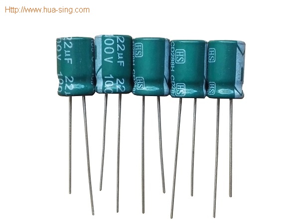
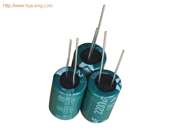
CD288H High Frequency Low Impedance Capacitors
- Series: CD288H
- Working Voltage Range: 6.3V~450VDC
- Capacitance Range: 0.47uF~15000uF
- Working Temperature: -55~+105°C
- Load Life: 8000 hours at +105℃
- Application: Used in high frequency and low impedance Circles.
 (※Click this button to inquiry)
Download Product Manual (PDF file) Send an E-mail to us!
CD288H Radial Leads Aluminum Electrolytic Capacitors High Frequency Low Impedance Capacitors
Feature:
● 105°C, 8000Hours.
● RoHS Compliant.
Application:
● Excellent frequency used in high frequency and low impedance.
| UR(V) CR(μF) |
6.3V(0J) | 10V(1A) | ||||||
| øDxL(mm) | Z(Ω) | I~(mA) 105°C 100KHz | øDxL(mm) | Z(Ω) | I~(mA) 105°C 100KHz | |||
| 20°C/100KHz | -10°C/100KHz | 20°C/100KHz | -10°C/100KHz | |||||
| 22uF | ø5x11 | 0.6 | 1.2 | 180 | ø5x11 | 0.6 | 1.2 | 180 |
| 33uF | ø5x11 | 0.6 | 1.2 | 180 | ø5x11 | 0.6 | 1.2 | 180 |
| 47uF | ø5x11 | 0.6 | 1.2 | 180 | ø5x11 | 0.6 | 1.2 | 180 |
| 82uF | - | - | - | - | ø5x11 | 0.65 | 1.3 | 175 |
| 100uF | ø5x11 | 0.65 | 1.3 | 175 | ø5x11 | 0.6 | 1.2 | 180 |
| 150uF | ø6.3x11 | 0.25 | 0.5 | 280 | ø6.3x11 | 0.25 | 0.5 | 290 |
| 180uF | - | - | - | - | ø6.3x11 | 0.25 | 0.5 | 290 |
| 220uF | ø6.3x11 | 0.25 | 0.5 | 290 | ø6.3x11 | 0.25 | 0.5 | 290 |
| 330uF | ø8x11.5 | 0.25 | 0.5 | 290 | ø8x11.5 | 0.17 | 0.34 | 488 |
| 470uF | ø8x11.5 | 0.17 | 0.34 | 488 | ø8x11.5 | 0.117 | 0.234 | 555 |
| 560uF | ø8x11.5 | 0.117 | 0.234 | 555 | - | - | - | - |
| 680uF | ø10x12.5 | 0.12 | 0.24 | 613 | ø10x12.5 | 0.09 | 0.18 | 755 |
| 820uF | ø8x16 | 0.085 | 0.17 | 730 | - | - | - | - |
| 1000uF | ø10x12.5 | 0.09 | 0.18 | 755 | ø10x16 | 0.068 | 0.136 | 1050 |
| 1200uF | ø8x20 | 0.065 | 0.13 | 995 | ø10x20 | 0.052 | 0.104 | 1220 |
| 1500uF | ø10x20 | 0.052 | 0.104 | 1220 | ø10x20 | 0.052 | 0.104 | 1220 |
| 2200uF | ø12.5x20 | 0.045 | 0.09 | 1400 | ø12.5x20 | 0.038 | 0.076 | 1655 |
| 2700uF | ø10x25 | 0.035 | 0.07 | 1815 | ø12.5x25 | 0.03 | 0.06 | 1945 |
| 3300uF | ø12.5x20 | 0.038 | 0.076 | 1655 | ø12.5x25 | 0.03 | 0.06 | 1945 |
| 3900uF | ø12.5x25 | 0.03 | 0.06 | 1945 | ø14x31.5 | 0.022 | 0.044 | 2510 |
| 4700uF | ø16x25 | 0.028 | 0.056 | 2220 | ø16x25 | 0.022 | 0.044 | 2120 |
| 5600uF | ø14x31.5 | 0.022 | 0.044 | 2510 | ø16x25 | 0.022 | 0.044 | 2555 |
| 6800uF | ø16x25 | 0.022 | 0.044 | 2555 | ø16x31.5 | 0.018 | 0.036 | 3010 |
| 8200uF | ø16x31.5 | 0.018 | 0.036 | 3010 | ø16x35.5 | 0.016 | 0.032 | 3150 |
| 10000uF | ø16x31.5 | 0.02 | 0.04 | 3150 | ø18x35.5 | 0.015 | 0.03 | 3680 |
| 12000uF | ø18x31.5 | 0.016 | 0.032 | 3635 | - | - | - | - |
| 15000uF | ø18x35.5 | 0.015 | 0.03 | 3680 | ø18x40 | 0.014 | 0.028 | 3800 |
| / | ||||||||
| UR(V) CR(μF) |
16V(1C) | 25V(1E) | ||||||
| øDxL(mm) | Z(Ω) | I~(mA) 105°C 100KHz | øDxL(mm) | Z(Ω) | I~(mA) 105°C 100KHz | |||
| 20°C/100KHz | -10°C/100KHz | 20°C/100KHz | -10°C/100KHz | |||||
| 4.7uF | - | - | - | - | ø5x11 | 0.6 | 1.2 | 180 |
| 10uF | ø5x11 | 0.6 | 1.2 | 180 | ø5x11 | 0.6 | 1.2 | 180 |
| 22uF | ø5x11 | 0.6 | 1.2 | 180 | ø5x11 | 0.6 | 1.2 | 180 |
| 33uF | ø5x11 | 0.6 | 1.2 | 180 | ø5x11 | 0.6 | 1.2 | 180 |
| 39uF | - | - | - | - | ø5x11 | 0.6 | 1.2 | 175 |
| 47uF | ø5x11 | 0.6 | 1.2 | 180 | ø5x11 | 0.6 | 1.2 | 180 |
| 56uF | ø5x11 | 0.65 | 1.3 | 175 | - | - | - | - |
| 82uF | - | - | - | - | ø6.3x11 | 0.35 | 0.7 | 290 |
| 100uF | ø6.3x11 | 0.25 | 0.5 | 290 | ø6.3x11 | 0.25 | 0.5 | 290 |
| 120uF | ø6.3x11 | 0.25 | 0.5 | 290 | ø8x11.5 | 0.25 | 0.5 | 400 |
| 150uF | ø6.3x11 | 0.25 | 0.5 | 290 | ø8x11.5 | 0.117 | 0.234 | 555 |
| 180uF | ø8x11.5 | 0.23 | 0.46 | 400 | - | - | - | - |
| 220uF | ø8x11.5 | 0.117 | 0.234 | 555 | ø8x11.5 | 0.117 | 0.234 | 555 |
| 330uF | ø8x11.5 | 0.117 | 0.234 | 555 | ø10x12.5 | 0.09 | 0.18 | 755 |
| 470uF | ø10x12.5 | 0.09 | 0.18 | 755 | ø10x16 | 0.068 | 0.136 | 1050 |
| 560uF | - | - | - | - | ø10x20 | 0.052 | 0.104 | 1220 |
| 680uF | ø10x16 | 0.068 | 0.136 | 1050 | ø10x20 | 0.052 | 0.104 | 1220 |
| 820uF | ø10x20 | 0.052 | 0.104 | 1220 | ø10x25 | 0.045 | 0.09 | 1440 |
| 1000uF | ø10x20 | 0.052 | 0.104 | 1220 | ø12.5x20 | 0.038 | 0.076 | 1655 |
| 1200uF | ø10x25 | 0.045 | 0.09 | 1440 | - | - | - | - |
| 1500uF | ø12.5x20 | 0.038 | 0.076 | 1655 | ø16x25 | 0.022 | 0.044 | 1950 |
| 1800uF | - | - | - | - | ø14x31.5 | 0.025 | 0.05 | 2310 |
| 2200uF | ø12.5x25 | 0.03 | 0.06 | 1945 | ø16x25 | 0.026 | 0.052 | 2390 |
| 2700uF | ø14x25 | 0.025 | 0.05 | 2310 | ø16x25 | 0.022 | 0.044 | 2555 |
| 3300uF | ø16x25 | 0.026 | 0.052 | 2390 | ø16x31.5 | 0.018 | 0.036 | 3010 |
| 3900uF | ø16x25 | 0.022 | 0.044 | 2555 | ø16x35.5 | 0.016 | 0.032 | 3150 |
| 4700uF | ø16x31.5 | 0.018 | 0.036 | 3010 | ø18x35.5 | 0.015 | 0.03 | 3680 |
| 5600uF | ø16x35.5 | 0.016 | 0.032 | 3150 | - | - | - | - |
| 6800uF | ø18x35.5 | 0.015 | 0.03 | 3680 | ø18x40 | 0.014 | 0.028 | 3800 |
| 8200uF | ø18x35.5 | 0.015 | 0.03 | 3680 | - | - | - | - |
| 10000uF | ø18x40 | 0.014 | 0.028 | 3800 | - | - | - | - |
| / | ||||||||
| UR(V) CR(μF) |
35V(1V) | 50V(1H) | ||||||
| øDxL(mm) | Z(Ω) | I~(mA) 105°C 100KHz | øDxL(mm) | Z(Ω) | I~(mA) 105°C 100KHz | |||
| 20°C/100KHz | -10°C/100KHz | 20°C/100KHz | -10°C/100KHz | |||||
| 0.47uF | - | - | - | - | ø5x11 | 5 | 10 | 25 |
| 1uF | - | - | - | - | ø5x11 | 3.5 | 7 | 40 |
| 2.2uF | - | - | - | - | ø5x11 | 3 | 6 | 55 |
| 3.3uF | - | - | - | - | ø5x11 | 2.6 | 5.2 | 65 |
| 4.7uF | ø5x11 | 0.6 | 1.2 | 180 | ø5x11 | 2.3 | 4.6 | 90 |
| 10uF | ø5x11 | 0.6 | 1.2 | 180 | ø5x11 | 1.4 | 2.8 | 120 |
| 18uF | - | - | - | - | ø5x11 | 1.3 | 2.6 | 120 |
| 22uF | ø5x11 | 0.6 | 1.2 | 180 | ø5x11 | 1.2 | 2.4 | 170 |
| 27uF | ø5x11 | 0.65 | 1.3 | 175 | - | - | - | - |
| 33uF | ø5x11 | 0.6 | 1.2 | 180 | ø6.3x11 | 0.43 | 0.86 | 300 |
| 47uF | ø6.3x11 | 0.25 | 0.5 | 290 | ø6.3x11 | 0.43 | 0.86 | 300 |
| 56uF | ø6.3x11 | 0.25 | 0.5 | 290 | ø8x11.5 | 0.4 | 0.8 | 360 |
| 82uF | ø8x11.5 | 0.2 | 0.4 | 400 | ø8x11.5 | 0.234 | 0.468 | 485 |
| 100uF | ø8x11.5 | 0.117 | 0.234 | 555 | ø8x11.5 | 0.234 | 0.468 | 485 |
| 120uF | - | - | - | - | ø8x16 | 0.155 | 0.31 | 635 |
| 150uF | ø8x11.5 | 0.117 | 0.234 | 555 | ø10x12.5 | 0.162 | 0.324 | 615 |
| 180uF | - | - | - | - | ø8x20 | 0.12 | 0.24 | 860 |
| 220uF | ø10x12.5 | 0.09 | 0.18 | 755 | ø10x16 | 0.119 | 0.238 | 850 |
| 270uF | - | - | - | - | ø10x25 | 0.082 | 0.164 | 1200 |
| 330uF | ø10x16 | 0.068 | 0.136 | 1050 | ø10x20 | 0.09 | 0.18 | 1010 |
| 390uF | ø10x20 | 0.052 | 0.104 | 1220 | ø12.5x20 | 0.063 | 0.126 | 1480 |
| 470uF | ø10x20 | 0.052 | 0.104 | 1220 | ø12.5x20 | 0.06 | 0.12 | 1500 |
| 560uF | ø10x25 | 0.045 | 0.09 | 1440 | ø12.5x25 | 0.05 | 0.1 | 1832 |
| 680uF | ø12.5x20 | 0.038 | 0.076 | 1655 | ø12.5x25 | 0.05 | 0.1 | 1470 |
| 820uF | - | - | - | - | ø14x31.5 | 0.034 | 0.068 | 2285 |
| 1000uF | ø12.5x25 | 0.03 | 0.06 | 1945 | ø16x25 | 0.034 | 0.068 | 2235 |
| 1200uF | ø14x25 | 0.025 | 0.05 | 2310 | ø16x31.5 | 0.028 | 0.056 | 2700 |
| 1500uF | ø16x25 | 0.026 | 0.052 | 2390 | ø16x31.5 | 0.026 | 0.052 | 1970 |
| 1800uF | ø16x25 | 0.022 | 0.044 | 2555 | ø18x31.5 | 0.025 | 0.05 | 3000 |
| 2200uF | ø16x31.5 | 0.018 | 0.036 | 3010 | ø18x35.5 | 0.023 | 0.046 | 3100 |
| 2700uF | ø16x35.5 | 0.016 | 0.032 | 3150 | - | - | - | - |
| 3300uF | ø18x35.5 | 0.015 | 0.03 | 3680 | - | - | - | - |
| 4700uF | ø18x40 | 0.014 | 0.028 | 3800 | - | - | - | - |
| / | ||||||||
| UR(V) CR(μF) |
63V(1J) | 100V(2A) | ||||||
| øDxL(mm) | Z(Ω) | I~(mA) 105°C 100KHz | øDxL(mm) | Z(Ω) | I~(mA) 105°C 100KHz | |||
| 20°C/100KHz | -10°C/100KHz | 20°C/100KHz | -10°C/100KHz | |||||
| 0.47uF | - | - | - | - | ø5x11 | 43 | 86 | 20 |
| 1uF | - | - | - | - | ø5x11 | 20 | 40 | 30 |
| 2.2uF | - | - | - | - | ø5x11 | 9.8 | 19.6 | 44 |
| 3.3uF | - | - | - | - | ø5x11 | 6.6 | 13.2 | 58 |
| 4.7uF | ø5x11 | 4.7 | 5.4 | 68 | ø5x11 | 4.6 | 9.2 | 74 |
| 6.8uF | ø5x11 | 2.5 | 5 | 95 | ø5x11 | 3.5 | 7 | 95 |
| 10uF | ø5x11 | 2.1 | 4.1 | 110 | ø6.3x11 | 1.8 | 3.6 | 130 |
| 12uF | ø5x11 | 2 | 4 | 145 | - | - | - | - |
| 15uF | ø6.3x11 | 1.2 | 2.4 | 160 | ø8x11.5 | 0.83 | 1.66 | 180 |
| 18uF | - | - | - | - | ø8x11.5 | 0.8 | 1.6 | 200 |
| 22uF | ø6.3x11 | 0.71 | 1.42 | 250 | ø8x11.5 | 0.68 | 1.36 | 230 |
| 33uF | ø6.3x11 | 0.71 | 1.42 | 250 | ø10x12.5 | 0.46 | 0.92 | 320 |
| 39uF | ø8x11.5 | 0.7 | 1.4 | 330 | - | - | - | - |
| 47uF | ø8x11.5 | 0.342 | 0.684 | 360 | ø10x16 | 0.37 | 0.74 | 420 |
| 68uF | ø8x11.5 | 0.342 | 0.684 | 405 | ø10x20 | 0.3 | 0.6 | 490 |
| 82uF | - | - | - | - | ø10x25 | 0.25 | 0.5 | 540 |
| 100uF | ø10x12.5 | 0.256 | 0.512 | 535 | ø12.5x20 | 0.18 | 0.36 | 580 |
| 120uF | ø10x16 | 0.194 | 0.388 | 600 | - | - | - | - |
| 150uF | ø10x16 | 0.194 | 0.388 | 660 | ø12.5x25 | 0.13 | 0.26 | 710 |
| 180uF | ø10x20 | 0.147 | 0.294 | 885 | ø14x31.5 | 0.12 | 0.24 | 790 |
| 220uF | ø10x20 | 0.2 | 0.4 | 700 | ø16x25 | 0.1 | 0.2 | 890 |
| 270uF | ø12.5x20 | 0.09 | 0.18 | 1410 | - | - | - | - |
| 330uF | ø12.5x20 | 0.085 | 0.17 | 1285 | ø16x25 | 0.09 | 0.18 | 1080 |
| 390uF | ø12.5x25 | 0.07 | 0.14 | 1720 | ø18x25 | 0.083 | 0.166 | 1260 |
| 470uF | ø12.5x25 | 0.07 | 0.14 | 1470 | ø16x31.5 | 0.076 | 0.152 | 1310 |
| 560uF | - | - | - | - | ø18x31.5 | 0.068 | 0.136 | 1370 |
| 680uF | ø16x25 | 0.05 | 0.1 | 2160 | ø18x35.5 | 0.064 | 0.128 | 1410 |
| 820uF | ø16x31.5 | 0.043 | 0.086 | 2670 | - | - | - | - |
| 1000uF | ø16x31.5 | 0.043 | 0.086 | 2340 | ø18x40 | 0.047 | 0.094 | 1520 |
| 1200uF | ø18x31.5 | 0.032 | 0.064 | 2950 | - | - | - | - |
| 1500uF | ø18x35.5 | 0.03 | 0.06 | 3095 | - | - | - | - |
| 2200uF | ø18x40 | 0.028 | 0.056 | 3200 | - | - | - | - |
| / | ||||||||
| UR(V) CR(μF) |
160V(2C) | 200V(2D) | 250V(2E) | 315V(2F) | ||||
| øDxL(mm) | *I~(mA) | øDxL(mm) | *I~(mA) | øDxL(mm) | *I~(mA) | øDxL(mm) | *I~(mA) | |
| 0.47uF | ø6.3x11 | 12 | ø6.3x11 | 12 | ø6.3x11 | 12 | ø8x11.5 | 11 |
| 1uF | ø6.3x11 | 17 | ø6.3x11 | 17 | ø6.3x11 | 17 | ø8x11.5 | 16 |
| 2.2uF | ø6.3x11 | 25 | ø6.3x11 | 25 | ø8x11.5 | 29 | ø10x12.5 | 28 |
| 3.3uF | ø8x11.5 | 36 | ø8x11.5 | 36 | ø10x12.5 | 42 | ø10x12.5 | 34 |
| 4.7uF | ø8x11.5 | 43 | ø10x12.5 | 50 | ø10x12.5 | 50 | ø10x16 | 45 |
| 10uF | ø10x12.5 | 70 | ø10x16 | 80 | ø10x20 | 88 | ø10x20 | 72 |
| 22uF | ø10x20 | 130 | ø10x20 | 140 | ø12.5x25 | 155 | ø12.5x25 | 120 |
| 33uF | ø12.5x20 | 180 | ø12.5x25 | 190 | ø12.5x25 | 190 | ø16x25 | 155 |
| 47uF | ø12.5x25 | 220 | ø12.5x25 | 220 | ø16x25 | 230 | ø16x35.5 | 190 |
| 100uF | ø16x25 | 330 | ø16x31.5 | 335 | ø18x35.5 | 340 | ø18x40 | 285 |
| 220uF | ø18x35.5 | 500 | ø18x40 | 515 | ø20x40 | 525 | ø22x50 | 540 |
| 330uF | ø20x40 | 900 | ø22x40 | 1100 | ø22x50 | 1150 | - | - |
| 470uF | ø22x50 | 1200 | ø22x50 | 1310 | ø26x50 | 1350 | - | - |
| UR(V) CR(μF) |
350V(2V) | 400V(2G) | 450V(2W) | |||
| øDxL(mm) | *I~(mA) | øDxL(mm) | *I~(mA) | øDxL(mm) | *I~(mA) | |
| 0.47uF | ø8x11.5 | 11 | - | - | - | - |
| 1uF | ø10x12.5 | 17 | ø10x12.5 | 16 | ø10x12.5 | 18 |
| 2.2uF | ø10x16 | 31 | ø10x16 | 27 | ø10x20 | 29 |
| 3.3uF | ø10x16 | 38 | ø10x20 | 36 | ø12.5x20 | 41 |
| 4.7uF | ø10x20 | 49 | ø10x20 | 43 | ø12.5x20 | 49 |
| 10uF | ø12.5x20 | 82 | ø12.5x20 | 72 | ø16x25 | 75 |
| 22uF | ø16x25 | 130 | ø16x25 | 110 | ø16x31.5 | 115 |
| 33uF | ø16x31.5 | 160 | ø16x31.5 | 140 | ø18x35.5 | 145 |
| 47uF | ø18x35.5 | 200 | ø18x35.5 | 170 | ø20x40 | 175 |
| 100uF | ø20x40 | 290 | ø22x50 | 350 | ø26x50 | 350 |
| 220uF | ø26x50 | 550 | - | - | - | - |
Datasheet(PDF) of CD288H Radial Lead Aluminum Electrolytic Capacitors, Please Contact us.
Send us the specification you need.
ESR in Aluminum Electrolytic Capacitors
For medium and high voltage applications, low loss aluminum electrolytic capacitors are required. Low ESR capacitors have less power losses and internal heating problems as compared to high ESR capacitors. Apart from lowering performance, high ESR values reduce the life of an aluminum electrolytic capacitor. In addition, a low ESR value allows a greater ripple current capacity to be achieved.
In an aluminum electrolytic capacitor, the aluminum anode, cathode foils, electrolyte, and tabs contribute to the overall ESR of the capacitor. The value of resistance from each source mainly depends on frequency and temperature. At low frequencies and low temperatures, the aluminum oxide makes the largest contribution to the overall ESR. On the other hand, at high frequencies and high temperatures, the largest contribution to the overall ESR comes from the electrolyte. Generally, under application conditions, paper combinations and the electrolyte are the primary sources of equivalent series resistance in these capacitors.
Polymer and hybrid (combining polymer and wet electrolyte) electrodes with significantly lower and more stable ESR are available on the market as well, that address most of the disadvantages of the wet electrolytic capacitors reducing the ohmic losses, dry out effect (reliability and stability improvement) and ESR temperature dependency.
The ESR value of an aluminum electrolytic capacitor is dependent on thickness and density of paper separators. To minimize equivalent series resistance, thicker and denser separators are not recommended.Use of many tabs and high conductivity electrolyte material helps to reduce ESR in aluminum electrolytic capacitors. The tab connections, foils, and paper separators can be tailored to produce a specific resistance contribution to the overall equivalent series resistance.
ESR with frequency capacitor technologies comparison
Capacitors-ESR-vs-frequency
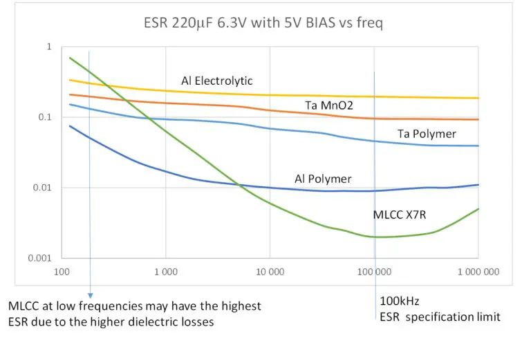
Fig.3 Comparison of different capacitor technologies 220uF 6.3V ESR with frequency
ESR is used to characterize capacitors losses mainly in higher frequency domain with standard reference frequency at 100kHz. ESR with frequency chart is illustrating losses in the entire frequency spectrum. As discussed above, the low frequency losses below around 1kHz are driven by “slower” polarization and losses in dielectric layers, mid frequencies (~ 1kHz to 10kHz) are driven by internal construction losses (such as conductivity of internal structure and electrolyte), the high frequencies >100kHz are driven by mostly ohmic losses of terminations, contacts etc.
Referring to Fig.3. MLCC capacitors are exhibiting lowest ESR values compare to other technologies referred to a standard specification frequency 100kHz thanks to its multilayer structure. This is a beneficial for smoothing of higher frequencies and fast spikes for applications such as switching power supplies. However, at low frequencies, MLCC class II capacitors are featuring higher ESR(and DF) compare to other technologies. Thus in practical example in case of low frequency spike present (such as 50-216Hz often seen) it is more efficient to use the MLCCs in parallel with some aluminium or tantalum electrolytic capacitors.
Click to search products

There are some other products you may be intersted in , please click to know about the details.
Aluminum Capacitors Miniature General Purpose 39D Aluminum Powerlytic Electrolytics Capacitors SYB Surface Mount Type Capacitor SA Conductive Polymer Capacitor Low ESR RVK Low Leakage Chip Electrolytic Capacitor
Friend Link:
Alibaba Store
Copyright @ 2025HUASING all rights reserved. >> Site Map 