- Home
- Products
-
- Film Capacitors
- Polyester Film
- High Voltage
- Polypropylene Film
- Paper Film
- Polystyrene film
- Interference Suppression
- High Voltage Pulse/impluse
- AC Voltage
- Electric Power Train
- SMD / Chip
- For Power Electronic
- Electric Railway Signalling
- Capacitive Divider AC
- Water Cooled Resonant Capacitor
- Polycarbonate Film
- Polyhenylene Sulfide Film
- PTFE Teflon Film
- Polyethylene Naphthalate Film
- Precision Film
-
 Tel:86 0513 65085106 Fax:86 0513 81164838 See more products, please click on the products center > >
- About Us
- News
- Project
- Service
- HR
- Feedback
- Contact Us
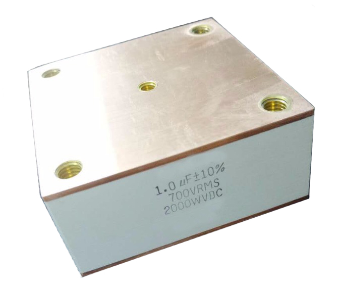
MX41 BA1 Water Cooled Resonant Capacitor
- Series: MX41 BA1
- Working Voltage Range: 400VAC - 1100VAC
- Capacitance Range: 0.1uF - 5uF
- Working Temperature: -40℃~+85℃
- Load Life: 100000h at UN and 70℃,30000h at Urms
- Application: Widely used in high power and high frequency resonant devices
 (※Click this button to inquiry)
Download Product Manual (PDF file) Send an E-mail to us!
MX41 BA1 Water Cooled, Conduction Cooled Capacitors
APPLICATION
Induction heating, heat treatment, plasma applications, resonant circuits, medical imaging, wireless power transfer, EV (electric vehicle) charging, IPT, high frequency inverters, etc.
ELECTRICAL CHARACTERISTICS
Conduction water-cooled
Polypropylene dielectric
Low dissipation factor(tgδ),low ESL and low ESR
High voltage, high frequency and high dv/dt,
High current resistance, excellent heat dissipation
TECHNICAL DATA
| Reference standards | GB/T 3984-2004 IEC 60110.1 | |
| Operating temperature range | -40℃~+85℃ | |
| Capacitance range | 0.1μF~5μF | |
| Rated capacitance | 100kVar-1500 kVar | |
| Rated voltage | 400VAC-1100VAC | |
| Tolerance | ±5% ±10% | |
| Test voltage between terminals | 1.5UNAC 10s | |
| 3.5UNDC 10s at 25℃±5℃ | ||
| Dissipation factor | tgδ≤5×10⁻⁴ at 25℃±5℃,1kHz | |
| Insulation resistance | R•C≥3000s,at 100VDC,25℃±5℃,60s | |
| Life expectancy | 100000h at UN and 70℃,30000h at Urms | |
| Part Number | Rated Voltage Vrms | Nominal Capaciance μF at 1Khz | Max Irms A | Max Power kVar | Freq Range @Full Power (kHz) |
ESR mΩ |
Dimension(mm) | Case Code | Replacment CSP 305B/600 |
||
| L | H | T | |||||||||
| MX41401405JBA1301-01 | 400 | 4.0 | 800 | 300 | 74.6-84.9 | 0.2 | 80 | 80 | 36.5 | BA1 | - |
| MX41501155JBA1301-01 | 500 | 1.5 | 650 | 300 | 127.3-149.5 | 0.4 | 80 | 80 | 36.5 | BA1 | 155HC4500K2UM8 |
| MX41501265JBA1301-01 | 500 | 2.6 | 750 | 300 | 73.5-114.8 | 0.3 | 80 | 80 | 36.5 | BA1 | 265HC3500K4VM6 |
| MX41601105KBA1301-01 | 600 | 1.0 | 650 | 300 | 132.7-1224 | 0.4 | 80 | 80 | 36.5 | BA1 | 105HC3600K4TM6 |
| MX41601125KBA1301-01 | 600 | 1.2 | 650 | 300 | 110.6-186.9 | 0.4 | 80 | 80 | 36.5 | BA1 | 125HC3600K4TM6 |
| MX41701244KBA1201-01 | 700 | 0.24 | 350 | 200 | 270.8-406.4 | 1.3 | 80 | 80 | 36.5 | BA1 | 254HC3700K4TM6 |
| MX41701334KBA1301-01 | 700 | 0.33 | 500 | 300 | 295.4-402 | 1.0 | 80 | 80 | 36.5 | BA1 | 334HC3700K4TM6 |
| MX41701664KBA1301-01 | 700 | 0.66 | 500 | 300 | 147.7-201 | 0.8 | 80 | 80 | 36.5 | BA1 | 664HC3700K4TM6 |
| MX41701684JBA1301-01 | 700 | 0.68 | 500 | 300 | 143.4-195 | 0.8 | 80 | 80 | 36.5 | BA1 | - |
| MX41102334KBA1301-01 | 1000 | 0.33 | 500 | 300 | 144.8-402 | 1.0 | 80 | 80 | 36.5 | BA1 | 334HC4102K2EM8 |
| MX41102664KBA1301-01 | 1000 | 0.66 | 500 | 300 | 72.4-201 | 0.8 | 80 | 80 | 36.5 | BA1 | 664HC4102K2EM8 |
| MX41102664KBA1401-01 | 1000 | 0.66 | 600 | 400 | 96.5-217 | 0.8 | 80 | 80 | 37.5 | BA1 | 664HC4102K4TM6 |
| MX41501305JBA1401-01 | 500 | 3.0 | 800 | 400 | 84.9 | 0.3 | 80 | 80 | 36.5 | BA1 | 505HC3400K4TM6 |
| MX41401505KBA1401-01 | 400 | 5.0 | 1000 | 400 | 79.6 | 0.2 | 80 | 80 | 36.5 | BA1 | 505HC3400K4VM6 |
Replacement parts of 155HC4500K2UM8,265HC3500K4VM6,105HC3600K4TM6,125HC3600K4TM6,254HC3700K4TM6,334HC3700K4TM6,664HC3700K4TM6,
334HC4102K2EM8,664HC4102K2EM8,664HC4102K4TM6,505HC3400K4TM6,505HC3400K4VM6
Above is gerneral purpose specificaton, we can custom design according to customers' requirement.334HC4102K2EM8,664HC4102K2EM8,664HC4102K4TM6,505HC3400K4TM6,505HC3400K4VM6
More specification please inquiry us.
Send us ORDER CODE for quote.
Guide to Using Water cooled Capacitors
1. Choosing the Best Capacitor for Your Needs
When choosing a capacitor for an application, select a capacitor with maximum rated voltage RMS, current and reactive power that most closely matches the highest operating voltage and frequency of the application. Take into account any ripple and any DV bias that can occur during operation, as even momentarily over voltage damages the capacitor and reduces its life time. The maximum ratings appear clearly on the data sheet of each capacitor.
The reactive power formula is:
Qc= V2rms x C x 2πf x 10-6
where
Qc is reactive power in kVAr
Vrms is RMS voltage in volts
C is capacitance in µF
f is frequency in kHz
2. Proper Cooling and Termination for Power Capacitors
conduction-cooled power capacitors handle a large amount of power in relatively small volume. In order to operate correctly, capacitors must be terminated properly to ensure uniform cooling of all internal elements.
Four critical requirements must be addressed when using conduction cooled capacitors:
1. Cooling. The entire area of the capacitor’s contacts surface must be placed in contact with the heat sink using a thermal conductive paste to ensure optimal heat conductance. This is particularly critical when the capacitor is working at its maximum limits. Never tighten the bolts beyond the maximum allowed torque.
2. Conduction losses. Most power capacitors are able to supply hundreds of amperes. When several capacitors are connected to a common collector, insufficient collectors’ surface area may result, due to the skin effect, in extreme heating of the bus bar where the current is collected, and overheating of the capacitor despite proper cooling.
3. Induction heating of capacitors. When several conduction-cooled capacitors are assembled between two bus bars, those located closest to the output terminals may experience induction heating. This situation should be avoided by mounting the capacitors as illustrated in diagram B or by building a low inductance path between the bus bars as illustrated in diagram C. The C-Cap technology overcomes this deficiency.
Click to search products

There are some other products you may be intersted in , please click to know about the details.
MX41 BA1 Water Cooled Resonant Capacitor MS series High Voltage Film Capacitor ZN11 damping absorption protection capacitor PEC Power Electronic Capacitors S/SS High Voltage 1pps Capacitors GA
Friend Link:
Alibaba Store
Copyright @ 2025HUASING all rights reserved. >> Site Map 